


ROYAL ENFIELD WORKSHOP MANUAL
PAGE 81
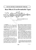
cap after unscrewing the three screws attaching it
to the hub. Unscrew the six Simmonds nuts and
drive out the pins.
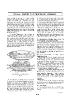
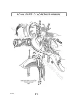
10. Refitting Ball Bearings
To refit the sprocket/brake drum bearing use
a hollow drift as shown in Fig. 6. The bearing is
first fitted to the fixed section of the spindle ; the
spindle and bearing are then entered into the
sprocket/brake drum and driven home, preferably
under a press or using light hammer blows.
The two bearings in the hub barrel are pressed
in using the drift part of E.4823. First assemble
the bearing into the circlip grooved end of the
barrel and fit the circlip. Replace the bearing
spacer, the slot in the spacer can be at either end
of the hub, and assemble the second bearing,
supporting the hub on the inner race of the other
bearing. If the drift part of E.4823 is not available
it is essential that the last bearing is assembled by
applying pressure to both inner and outer races
simultaneously to avoid pre-loading the two hub
barrel bearings.
11. Re-assembly of Brake Shoes and Operating
Cam into Cover Plate
No difficulty should be experienced in carrying
out these operations. Put a smear of grease on the
pivot pin and on the operating face of the cam ;
also on to the cylindrical bearing surface of the
operating cam if this has been removed. Fit the
operating lever and trunnion on its splines in a
position to suite the extent of wear on the linings
and secure the nut. The range of adjustment can
be extended by moving the lever on to a different
spline.
12. Final Re-assembly of Hub Before
Replacing Wheel
Before replacing the felt washers which form
the grease seals, pack all bearings with grease.
Recommended greases are Castrolease LM,
Mobilgrease M, Esso Multipurpose Grease H,
Energrease L2, Shell Retinax A or Marfak
Multipurpose 2. These are all medium heavy lime
soap or aluminium soap greases. The use of
H.M.P. greases, which have a soda soap base is
not recommended, as these tend to be slightly
corrosive if any damp finds its way into the hubs.
Make sure that the inside of the brake drum is
quite free from oil or grease, damp, etc. Replace
the felt washers, distance collars, the brake cover
plate assembly, speedometer drive gearbox,
distance collars and chain adjuster cams, the loose
section of the spindle and the spindle nut. The
wheel is then ready for re-assembly into the
machine.
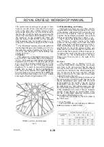
13. Wheel Rim
The wheel rim is WM2-17 in., plunged and
pierced with forty holes for spoke nipples. The
spoke holes are symmetrical, i.e., the rim can be
assembled to the hub either way round. The rim
diameter after building is 17.06 in., the tolerances
on the circumference of the rim shoulders where
the tyre fits being 53.642/53.582 in. The standard
steel measuring tape for checking rims is ¼ in.
wide, .011 in. thick, and its length is 53.702/53.642
in.
14. Spokes
The spokes are of the single-butted type,
8-10-in. gauge with 90° countersunk heads,. thread
diameter .144 in., 40 threads per inch, thread form
British Standard Cycle. The inner spokes are 5
11
/
16
in. long, and the outer spokes, 5
3
/
4
in. long. All
spokes initially have an angle of bend of
approximately 100°. The outer spokes are hit with
a hide or wooden mallet after building the wheel
but before finally truing it, so as to give a more
acute angle of approximately 80°.
15. Wheel Building and Truing
The spokes are laced one over two, and the
wheel rim must be built central in relation to the
outer faces of the distance collars. The rim should
be trued as accurately as possible, the maximum
permissible run-out both sideways and radially
being plus or minus
1
/
32
in.
16. Tyre
The standard tyre is Dunlop 3.25-17 in.
Universal tread. When removing the tyre always
start close to the valve and see that the edge of the
cover at the other side of the wheel is pushed
down into the well in the rim. When replacing the
tyre, fit the part by the valve last, also with the
edge of the cover at the other side of the wheel
pushed down into the well.
If the correct method of fitting and removal of
the tyre is adopted it will be found that the covers
can be manipulated quite easily with the small
levers supplied in the tool-kit. The use of long
levers and/or excessive force is liable to damage
the walls of the tyre. After inflation make sure that
the tyre is fitting evenly all the way round the rim.
A line moulded on the wall of the tyre indicates
whether or not the tyre is correctly fitted. If the
tyre has a white mark indicating a balance point,
this should be fitted near the valve.
17. Tyre Pressures
The recommended pressures for the rear tyre
are 16lbs per square inch for wheel loads not
exceeding 2001b., 18 lb. per square inch for loads
L6
www.hitchcocksmotorcycles.com
Summary of Contents for 250 CLIPPER
Page 40: ...ROYAL ENFIELD WORKSHOP MANUAL PAGE 40 w w w h i t c h c o c k s m o t o r c y c l e s c o m ...
Page 46: ...ROYAL ENFIELD WORKSHOP MANUAL PAGE 46 w w w h i t c h c o c k s m o t o r c y c l e s c o m ...
Page 52: ...ROYAL ENFIELD WORKSHOP MANUAL PAGE 52 w w w h i t c h c o c k s m o t o r c y c l e s c o m ...
Page 62: ...ROYAL ENFIELD WORKSHOP MANUAL PAGE 62 w w w h i t c h c o c k s m o t o r c y c l e s c o m ...
Page 72: ...ROYAL ENFIELD WORKSHOP MANUAL PAGE 72 w w w h i t c h c o c k s m o t o r c y c l e s c o m ...
Page 76: ...ROYAL ENFIELD WORKSHOP MANUAL PAGE 76 w w w h i t c h c o c k s m o t o r c y c l e s c o m ...
Page 88: ...ROYAL ENFIELD WORKSHOP MANUAL PAGE 88 w w w h i t c h c o c k s m o t o r c y c l e s c o m ...


