


ROYAL ENFIELD WORKSHOP MANUAL
PAGE 77
L6
Rear Wheel
(Quickly Detachable Type with 6in. diameter Brake
and Full-Width Hub)
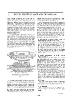
1. Description
The main portion of the wheel can be
removed from the machine without disturbing the
chain or brake, or removing the mudguard. The
wheel incorporates the well-known Royal Enfield
cush drive and also a 6 in. internal expanding
brake.
2. Removal and Replacement of Main Portion
of Wheel, for Tyre Repairs, etc.
With the machine on the centre stand unscrew
the righthand spindle nut and withdraw the loose
section of the spindle, together with the chain
adjuster cam, preferably marking this to ensure
that it is replaced in the same position. Now slide
the distance collar out of the fork end and lift away
the speedometer drive gearbox, which can be left
attached to the driving cable. The spacing collar
and the felt washer behind it may now be removed
to prevent risk of them falling out when
manipulating the tyre. If, however, these are too
tight a fit in the hub to come out easily they may
be left in place. The main body of the wheel can
now be pulled across to the right-hand side of the
machine, thus disengaging the six driving pins
from the cush drive shell. Standing on the
left-hand side of the machine, adjacent to the rear
mudguard, lean the machine to the left until the
wheel can be rolled out between the mudguard and
the righthand fork end.
When replacing the main portion of the
wheel reverse the foregoing procedure, taking
care, when replacing the speedometer drive
gearbox, that the driving dogs inside the
gearbox engage with the slots in the end of the
hub barrel. The cush drive shell can be
prevented from rotating when turning the wheel
to engage the six driving pins if the machine is
placed in gear or the rear brake is operated.
Before tightening the centre spindle make sure
that the speedometer drive gearbox is correctly
positioned so that there is no sharp bend in the
driving cable.
3. Removal and Replacement of Complete
Wheel for Access to Brake
Place the machine on the centre stand and
remove the rear mudguard unit.* Remove the
five screws securing the two parts of the
chaincase to the brake cover plate and remove
the rear portion of case**. Disconnect the rear
driving chain at the spring link and loop the top
end of the chain over the tag provided at the top
of the fixed portion of the chaincase. Pull on the
other end of the chain and allow it to hang from
the lower tunnel of the case. This will ensure
that the chain is not lost in the case. Unscrew
*See Section H6,
subsection 3
**If fitted.
www.hitchcocksmotorcycles.com
Summary of Contents for 250 CLIPPER
Page 40: ...ROYAL ENFIELD WORKSHOP MANUAL PAGE 40 w w w h i t c h c o c k s m o t o r c y c l e s c o m ...
Page 46: ...ROYAL ENFIELD WORKSHOP MANUAL PAGE 46 w w w h i t c h c o c k s m o t o r c y c l e s c o m ...
Page 52: ...ROYAL ENFIELD WORKSHOP MANUAL PAGE 52 w w w h i t c h c o c k s m o t o r c y c l e s c o m ...
Page 62: ...ROYAL ENFIELD WORKSHOP MANUAL PAGE 62 w w w h i t c h c o c k s m o t o r c y c l e s c o m ...
Page 72: ...ROYAL ENFIELD WORKSHOP MANUAL PAGE 72 w w w h i t c h c o c k s m o t o r c y c l e s c o m ...
Page 76: ...ROYAL ENFIELD WORKSHOP MANUAL PAGE 76 w w w h i t c h c o c k s m o t o r c y c l e s c o m ...
Page 88: ...ROYAL ENFIELD WORKSHOP MANUAL PAGE 88 w w w h i t c h c o c k s m o t o r c y c l e s c o m ...


