


ROYAL ENFIELD WORKSHOP MANUAL
PAGE 80
L6
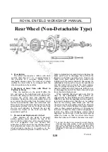
the cush drive shell, thus permitting only a small
amount
of
angular
movement
of
the
sprocket/brake drum relative to the hub barrel
and transmitting both driving and braking torques
and smoothing out harshness and irregularity in
the former.
If the cush drive rubbers become worn so that
the amount of free movement measured at the tyre
exceeds ½ in. to 1 in. the rubbers should be
replaced. To obtain access to them, remove the
complete wheel as described above, then unscrew
the loose section of the spindle completely. The
main portion of the wheel can then be lifted away
from the assembly, consisting of the fixed portion
of the spindle, sprocket/brake drum complete with
brake and the cush drive shell. Now remove the
brake cover plate complete with brake shoes as
described above, and unscrew the three nuts at the
back of the cush drive shell after bending back the
locking washers. The three studs are brazed to the
lockring and should be driven out of the cush drive
shell, each a little at a time to avoid distorting the
lockring or bending the studs. The sprocket/brake
drum can now be separated from the cush drive
shell and the six cush drive rubbers lifted out.
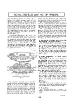
When re-assembling the cush drive the entry of
the vanes between the rubbers will be facilitated if
the latter are fitted into the driving shell first and
then tilted. The rubbers should be liberally painted
with soapsuds to facilitate entry of the vanes.
Grease the inner face of the lockring before
assembling and tighten the three nuts down solid as
there is a shoulder on the stud which prevents
tightening of the nuts from locking the operation
of the cush drive. Do not forget to bend up the
tabs of the three locking washers.
When re-assembling the cush drive, coat the
inside of the bore of the sprocket/brake drum
liberally with grease where it fits over the hub
barrel.
7. Removal of Ball Bearings
To remove the ball bearings, take the complete
wheel out of the machine and separate the main
portion of the wheel from the sprocket/brake
drum, cush drive shell assembly as described
above. To remove the bearing from the
sprocket/brake drum first remove the brake cover
plate complete with brake shoe assembly ; then
remove the distance collar and unscrew the
bearing retaining ring with peg spanner. Now
screw the loose section of the spindle into the
fixed section and drive out the bearing by hitting
the hexagon-headed end of the loose section of
the spindle.
To remove the bearings from the loose half of
the hub barrel, first lift away the distance collar,
speedometer drive gearbox, the spacing collar and
the felt washer. Remove the bearing retaining
circlip from the driving sprocket end of the barrel.
Between the two bearings is a spacer slotted at one
end to enable a drift to be used on the bearing at
that end. Remove this bearing first, then enter the
loose section of the spindle into the spacer and
drive out the remaining bearing by means of a
hammer and drift applied to the hexagon-headed
end of the spindle.
8. Hub Bearings
These are deep-groove single-row journal ball
bearings,
5
/
8
in. i.d. by 1
9
/
16
in. o.d. by
7
/
16
in.
wide. The Skefko Part Number is RLS5.
Equivalent bearings of other makes are Hoffmann
LS7, Ransome and Marles LJ.5/8 and Fischer LS7.
9. Removal of Hub Driving Pins
To remove the six driving pins from the
aluminium full width hub, first remove the hub
www.hitchcocksmotorcycles.com
Summary of Contents for 250 CLIPPER
Page 40: ...ROYAL ENFIELD WORKSHOP MANUAL PAGE 40 w w w h i t c h c o c k s m o t o r c y c l e s c o m ...
Page 46: ...ROYAL ENFIELD WORKSHOP MANUAL PAGE 46 w w w h i t c h c o c k s m o t o r c y c l e s c o m ...
Page 52: ...ROYAL ENFIELD WORKSHOP MANUAL PAGE 52 w w w h i t c h c o c k s m o t o r c y c l e s c o m ...
Page 62: ...ROYAL ENFIELD WORKSHOP MANUAL PAGE 62 w w w h i t c h c o c k s m o t o r c y c l e s c o m ...
Page 72: ...ROYAL ENFIELD WORKSHOP MANUAL PAGE 72 w w w h i t c h c o c k s m o t o r c y c l e s c o m ...
Page 76: ...ROYAL ENFIELD WORKSHOP MANUAL PAGE 76 w w w h i t c h c o c k s m o t o r c y c l e s c o m ...
Page 88: ...ROYAL ENFIELD WORKSHOP MANUAL PAGE 88 w w w h i t c h c o c k s m o t o r c y c l e s c o m ...


