www.rovingnetworks.com
Version 1.0r 9/21/2012
54
RN -W IFLYCR -U M
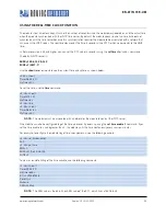
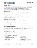
Table 23. GPIO Pin Alternate Function Bitmask
Bit
Signal Name
Direction
Function
0
GPIO4
Output
Disable the LED function so the I/O can be used as a GPIO pin.
1
GPIO5
Output
Disable the LED function so the I/O can be used as a GPIO pin.
2
GPIO6
Output
Disable the LED function so the I/O can be used as a GPIO pin.
3
Unused
-
-
4
GPIO4
Output
This pin goes high after the module has associated/authenticated and has an IP address.
5
GPIO5
Input
Set this pin high to trigger a TCP connection and low to disconnect.
6
GPIO6
Output
This pin goes high when the module is connected over TCP and low when disconnected.
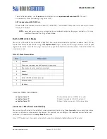
NOTE:
Bits 0 - 3 are mutually exclusive with bits 4 – 6, i.e.,
0x77
is an illegal value.
If you disable the LEDs using bits 0, 1, and 2, you can then use the
show i
command to read these GPIO pins. For
example, the
show i
command might return
Port=30
.
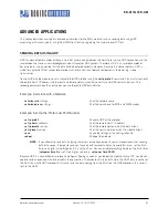
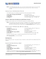
To use the alternate LEDs functions, use the following commands:
set sys iofunc 0x70
// Enable alternate function for GPIO4 - 6
save
// Store configuration
reboot
// Reboot the module
Controlling Connections with GPIO Pins
In embedded applications it is useful to monitor and control the status of the TCP/IP connection. To monitor and control
the module’s connection status, enable the alternate function of GPIO4 - 6. Using the alternate function for these GPIO
pins, the module connects to the stored remote host IP address and port when GPIO5 is driven high and disconnects
when driven low. You can monitor the TCP/IP connection status by reading GPIO6; it is high when connected and low
when not connected.
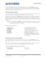
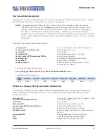
To configure the module to connect using GPIO5 and GPIO6, use the following commands:
set ip host
<
address
>
// Set the IP address of the remote host
set ip remote
<
value
>
// Set the IP port of the remote host
set sys iofunc 0x70
// Set alternate function for GPIO4 - 6
save
// Store configuration
reboot
// Reboot the module
After executing these commands, run your application or other software on the remote host that opens and listens on the
specified port. Then, connect GPIO5 to your embedded processor or other control signal. When GPIO5 is driven high, the
module attempts to connect. When GPI05 is driven low, the connection is closed.
NOTE:
Do not to drive the GPIO pin with more than 3.3-V DC or permanent damage to the module will occur.
If the connection to the remote host is successful, GPIO6 goes high. If you have set the
COMM OPEN
and
REMOTE
strings, the UART displays
*OPEN*
and the remote host displays
*HELLO*
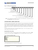
. Figure 11 shows the process of controlling
connection with the GPIO pins.


