10
PAX1 Motor Set Pressure Regulator
User Manual
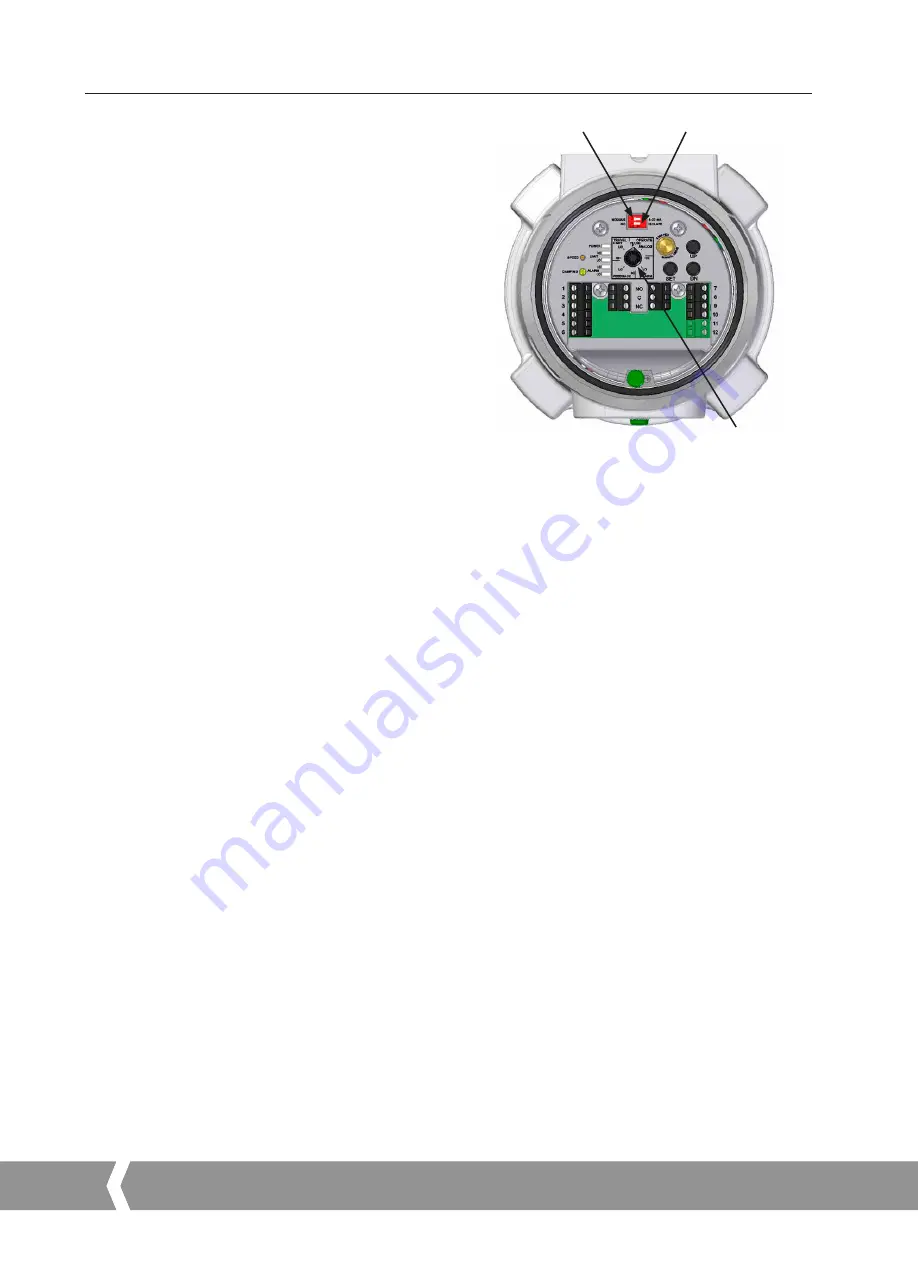
Setup switch
Eight position rotary SETUP switch, for setting control type
and configuring travel limits, Alarm points and Feedback
calibration.
Configuration DIP switches
SW1
selects 4-20 mA for analog control input or Modbus
communication control.
SW2, Isolate:
The Pulse control inputs are isolated from
the DC power supply providing power to the unit and must
be powered from a separate external power source. (
See
Figure 3
). This is useful for long runs of the control lines to
eliminate ground loops with local power supply and control
equipment.
SW2, NO:
The Pulse control input circuit is connected to the
DC power supply providing power to the unit. No external
control loop supply required. One side of the control switches
must be connected to the – power supply connection.
(
See Figure 4
).
Push button switches
UP:
Moves the pressure regulator setpoint to a higher
pressure.
DN:
Moves the pressure regulator setpoint to a lower
pressure.
SET:
Used in conjunction with the rotary SETUP switch to
set the pressure limits, alarm points, and analog feedback
calibration.
LED indicators
PWR:
Green, Supply voltage is between 11 and 30 VDC.
Red, Voltage is less than 11 VDC or greater than 30 VDC.
LIMIT HI:
Green, Hi limit not reached, thrust rod will move in
both directions. Red, Hi Limit reached, thrust rod will move
down only.
LIMIT LO:
Green, Lo limit not reached, thrust rod will move
in both directions. Red, Lo Limit reached, thrust rod will move
up only.
ALARM HI:
Green, Hi Alarm not reached, Hi Alarm relay not
energized. Red, Hi Alarm reached, Hi Alarm relay is energized.
NO contact is closed.
ALARM LO:
Green, Lo Alarm not reached, Lo Alarm relay
not energized. Red, Lo Alarm reached, Lo Alarm relay is
energized. NO contact is closed.
SW1
SW2
SETUP
switch
Figure 12
Speed potentiometer
20 turn. Adjusts actuator speed from 1.2 mm/min to
60 mm/min.
In order to get the utmost performance from the PAX1, the
motor speed range can be adjusted beyond its stall speed.
The actual maximum attainable operating speed will depend
on the supply voltage, and the maximum required thrust.
The maximum required thrust will depend on the pressure
regulator model and its pressure range.
If the motor stalls before the maximum pressure range can be
attained, reduce the motor speed.
Damping potentiometer
1 turn. Adjusts start and stop ramp speed rate. Use this
control to prevent hunting of the output about the setpoint.
Manual control
The actuator can be manually moved by manually turning
the motor through an 8 mm (
5
/
16
”) female hex socket
located through the hole in the top PCA cover near the SET
button. Turning the motor clockwise increases pressure,
counter clockwise decreases pressure. Take care not to drive
the actuator into its mechanical stops and over torque the
gearbox as damage to the gearbox may result.
6.
User Interface
A4
US
US
A4
US
A4
US
A4
Summary of Contents for FAIRCHILD PAX1
Page 1: ...PAX1 Motor Set Pressure Regulator User Manual...
Page 23: ...23 12 Notes...


