background image

Read Only

Both Directions

First Menu

Last Menu

Interface Feedback

The Centronik display interface includes various features that 
provide feedback to the operator. This ensures that changes to 
the configuration of the actuator can be confirmed and validated 
during the commissioning process. 

Arrow Identification 

During general menu navigation, each submenu/setting will have 
a set of behaviour arrows associated with it. This lets the operator 
know what can be achieved on the current screen. 

Solid blocks on the setting/menu indicate navigation is not 
possible. The function is read only. 

Arrows on the menu/setting indicate navigation is possible – both 
directions. The function is in edit mode. 

An inverse arrow on the left indicates you are viewing the first 
menu/setting or the lowest value. 

An inverse arrow on the right indicates you are viewing the last 
menu/setting or the highest value. 

Confirmation Feedback 

Whilst modifying settings or navigating through the various 
Centronik interface menus, it is important to recognise that a 
change has been accepted or saved. 

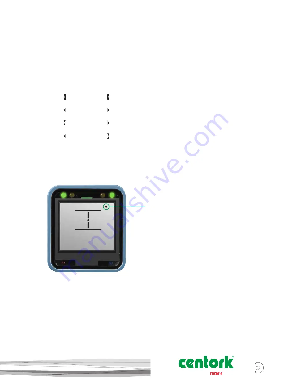
A small confirmation dot will be shown in the top right corner of 
the display if a valid input command has been recognised by the 
Centronik interface. 

For each movement, the confirmation dot will only be shown 
once the Open/Close selector returns to the default rest 
position.

Centronik Interface – Using the product

CLOSELIM
DEMO

A4

US

US

A4

US

A4

US

A4

A4

US

 US

 A4

 US

 A4

A4

US

5


Brand

Summary of Contents for centork CK Series

Page 1: ...Modular Design Electric Valve Actuators A Brand CKC CKRC Centronik Start Up Guide...

Page 2: ...we can fully support customer and end user requirements Over 1 000 service technicians are employed by our company partners and representatives providing the necessary worldwide infrastructure to full...

Page 3: ...ansmitter Receiver B Open C Close D Remote E Stop F Local B C D A F E Centronik Interface A Bluetooth Connection B Infrared Connection C Configuration Mode D Communication Feedback E Valve Position F...

Page 4: ...nput Navigate to next menu increase value confirm character Hold selector position for 3 seconds for special input function The Centronik Control Module can be configured using 2 different input metho...

Page 5: ...nu setting indicate navigation is possible both directions The function is in edit mode An inverse arrow on the left indicates you are viewing the first menu setting or the lowest value An inverse arr...

Page 6: ...r to PUB111 005 The arrow behaviour will indicate the setting value is in edit mode and blank spaces will also be filled see Fig 2 Fig 2 Default password shown in edit mode Confirm ROTORK as the passw...

Page 7: ...CK communication the Bluetooth Setting Tool must be aligned to the IrCK LED at all times Entering the User Password The password entry screen will be displayed with the default password visible Press...

Page 8: ...LIMIT OPEN SETT ACTION SEAT TORQ SET LIMIT TURNS TRQ LIM BP OPENING OP BP POSI CLOSING CL BP POSI Password Entry Process Main menu Language Settings Limit settings Close settings Direction to close St...

Page 9: ...in the open direction by 5 turns 10 turns for CK500 Press to edit SURE will show on the display press to confirm Once these steps are complete the Centronik display position should replicate the imag...

Page 10: ...nd CLOSING settings will enable torque limit bypass for the relevant direction of travel use and to enter the setting sub menu Press to edit select ON or OFF and press to save selection USER x PASSWOR...

Page 11: ...a mid travel position and confirm that none of the switches are active before beginning the test procedure 2 Test position switches in both directions using a flat screwdriver to turn LS TEST CW for...

Page 12: ...h state has changed will be seen on the Centronik display interface The status text bottom line will show TRQ T CLOS or TRQ T OPEN and the alarm status LED will illuminate red To confirm the normally...

Page 13: ...Torque Cam Clutch Screw 1 Move the valve to a mid travel position and loosen the Torque Cam Clutch 1 5 turns using a flat screwdriver 2 Adjust each Torque Cam to the desired value between min max by...

Page 14: ...limits have been set CAUTION Ensure the Torque Cam Clutch Screw is tightened enough to fully deform the spring washer underneath the screw head E Factory Calibration Fixings WARNING Do not adjust the...

Page 15: ...m the correct direction This is done to avoid the need to wind through the whole mechanism to reach the limit position The correct direction to approach the limit is shown by the arrow next to the Adj...

Page 16: ...he Adjustment Screw input 12 Perform two checks to confirm the OPEN limit position switch has been made correctly a The feel of the Adjustment Screw will noticeably change providing more mechanical re...

Page 17: ...other limit functions will not be available as they need to be intrusively set on the mechanism Centronik Interface Basic Settings Mechanical Switch Mechanism Password Entry Process Main menu Languag...

Page 18: ...o a mid travel position and confirm that none of the switches are active before beginning the test procedure 2 Test position switches in both directions using the LS TEST lever shown on the right side...

Page 19: ...Switch Mechanism move DOWN for open UP for close The status text bottom line will show TRQ T CLOS or TRQ T OPEN and the alarm status LED will illuminate red To confirm the normally closed control swi...

Page 20: ...n Disc CAUTION The AID cover orientation can be adjusted through 360 in 90 increments If this is a requirement then the following instructions must be adjusted by the same increment in the same direct...

Page 21: ...taining Screw by 1 turn whilst holding the CLOSE portion of the Position Disc 8 Rotate only the red OPEN portion of the disc so that OPEN reads horizontally and then hold both portions in place 9 Tigh...

Page 22: ...heel 2 Move the switch cam along the shaft against the spring to allow free rotation of the cam 3 Rotate the cam to ensure the desired switch behaviour is achieved The intermediate position switches c...

Page 23: ...ring diagram and POT Setting Information table below 5 Rotate the POT input gears until the Closed Limit is reported on the Centronik display or the measured resistance value has been reached 6 Refit...

Page 24: ...rk com The name Centork is a registered trademark Centork recognises all registered trademarks The Bluetooth word mark and logos are registered trademarks owned by Bluetooth SIG Inc and any use of suc...

Reviews: