5
x
Control unit operation
33
FA ROTEX Solaris RPS3 25M - 03/2010
5.2.9 Frost protectionfunction
When the frost protection is active, the Solaris solar system only operates when the switch-on condition is met and the collector
temperature "T
K
" exceeds the value of "T
K
save" (factory setting 70 °C). The circulation pump and, where installed, the booster
pump, are operated after switch-on for at least the time set in parameter "Time P2", even if the switch-off temperature condition
is already fulfilled before.
If required (e. g. with long runs of connection pipes outside), this minimum initial run time can be extended by the heating engineer
by presettable amount ("frost time"). This prevents the build-up of ice in the connecting pipe.
The status of the frost protection function "FR active" indicates whether the function is enabled or disabled (Image 5-4). The
heating engineer can switch the function on or off manually.
5.2.10 Plant leakage protection function
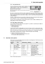
If, after switching on the pump(s), a minimum flow rate start phase "V1" as per Table 5-1 is not detected at the FlowSensor in
the filling time "Time P2", then there may be:
– a defect of the FlowSensor, or
– a leak in the Solaris system.
To prevent all the storage tank water being pumped out of the system in the event of a leak, the circulation pump and, where
installed, the booster pump, are switched off for 2 hours and the error message "W" flashes in the left-hand column of the display.
If this error occurs three times in succession without the start phase minimum flow rate "V1" being achieved, the connected
pump(s) switch(es) off permanently and the error message "F" appears in the left-hand column of the display.
•
Replace the defective FlowSensor or repair the leak.
•
Cancel the error message by switching off and on at the main switch.
The system is ready for operation once more.
5.3
Adjustments and menu guidance
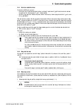
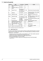
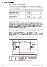
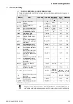
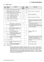
Table 5-2 gives an overview of the available measurement points and the associated display formats. Table 5-3 shows a summary
of the displays for the calculated parameters.
Table 5-2 Overview of measurement points
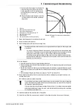
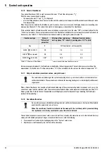
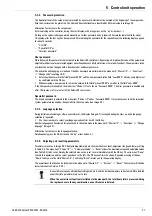
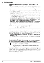
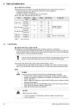
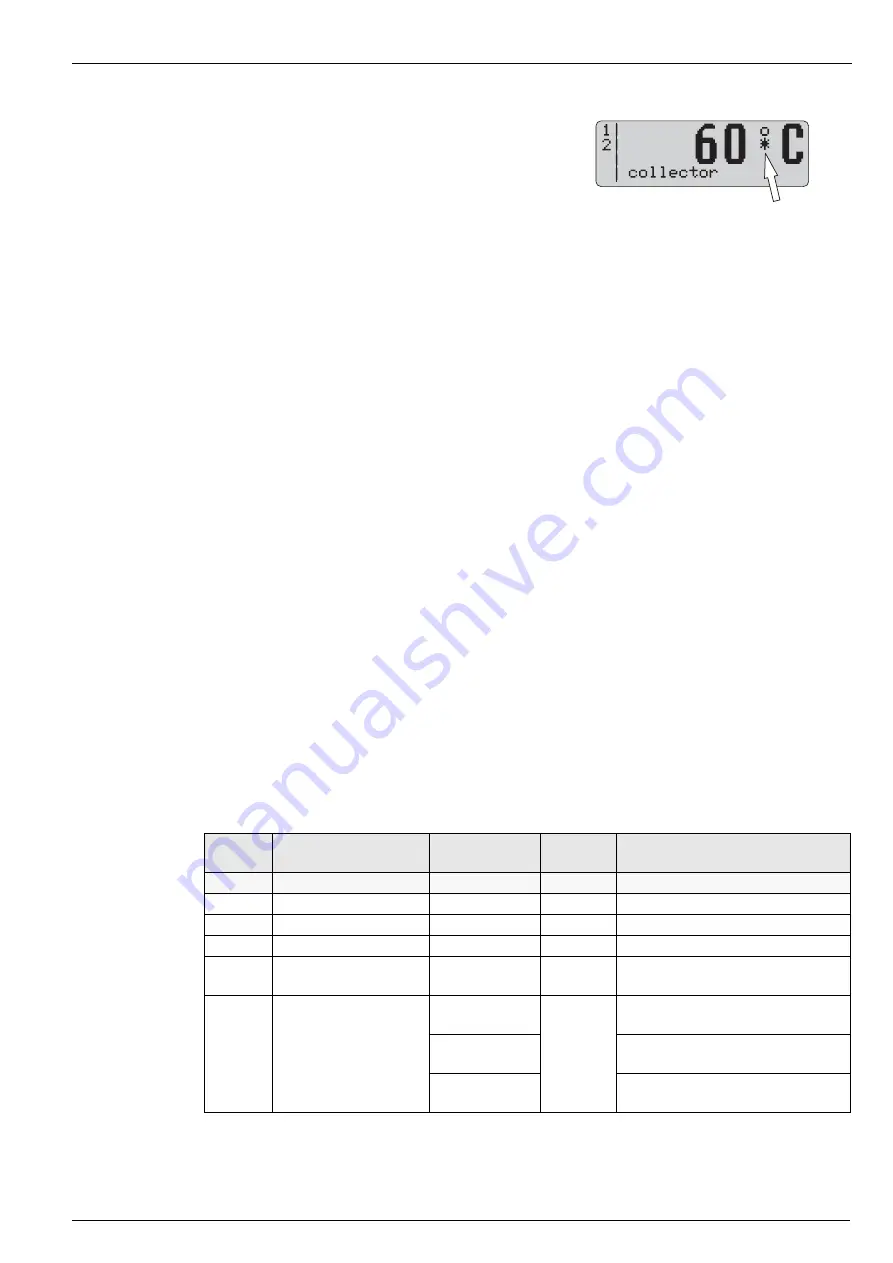
The frost protection function is activated as soon as the controller measures
a collector temperature "T
K
" below "T frost" (factory-defined frost
protection temperature). It remains active for the next 24 hours after the
temperature rises above this limit again.
When the frost protection is active, a star symbol is shown in the standard
temperature display.
Illustration 5-2 Operating display when frost
protection is active
Measuring
point
Name
Measuring range Resolution
Sensor
Display
T
K
Collector temperature
-30 to 250 °C
1 K
Pt 1000 temperature sensor
T
R
Return temperature
0 to 100 °C
1 K
PTC temperature sensor
T
S
Storage tank temperature
0 to 100 °C
1 K
PTC temperature sensor
T
V
Flow temperature
0 to 100 °C
1 K
FlowSensor (all types) with
voltage output 0.5 to 3.5 V
V
Flow rate
0.0 to 20.0 l/min
0.1 l/min
FlowSensor FLS20 with
voltage output 0.36 to 3.5 V
0.0 to 40.0 l/min
FlowSensor FLS40 with
voltage output 0.36 to 3.5 V
0.0 to 100.0 l/min
FlowSensor FLS100 with voltage output
0.36 to 3.5 V

