background image

x

 Control unit operation

32

FA ROTEX Solaris RPS3 25M - 03/2010

5.2.6 Solaris FlowSensor

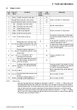
The optional FlowSensor (FLS) is used to measure flow rate "V" and flow temperature "T

V

".

With the sensor connected and working:
– the measured values "V" and "T

V

" are displayed.

– after the filling procedure, the control unit works with the actual system temperature difference between inflow and return 

flow temperatures.

When the system has detected the FlowSensor, and if a sensor is faulty or is removed, the display shows a corresponding error 
message (see Chapter 6.1). The system then works in the emergency mode without the FlowSensor.

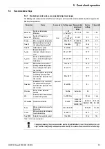
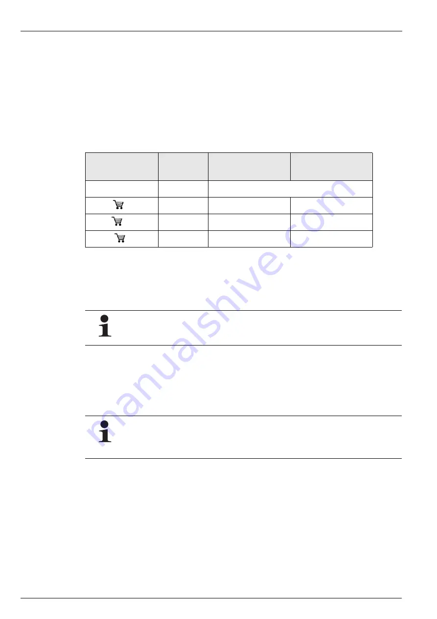
If the controller detects a FlowSensor after a new installation or a specialist reset, the value "100" is automatically set for the 
"FLS active" parameter. The correct parameter value for the FlowSensor installed in the system must always be checked and set 
if necessary (see Table 5-1). The FlowSensor can be deactivated by entering the parameter value "0".

No error message is displayed if the FlowSensor is disabled by the heating specialist. The controller now works without the 
measurement for the flow rate. The flow temperature "T

V

" is thus assumed to be the same as the collector temperature "T

K

".

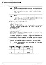
5.2.7 Output calculation, maximum values, and yield count

When a Solaris FlowSensor is connected, calculation and balancing of the system operating data is carried out, such as e. g. the 
current heat output and the solar heat yield. The maximum and calculated values can be requested on the display (see Chap. 5.3). 
Values greater than 0 which have not been deleted are still displayed even after disconnecting or disabling the FlowSensor 
(without further updating).

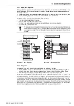
5.2.8 Overallresetfunction

The controller responds to an overall reset with a new start (self-test), whereby all parameters are set to their default (factory) 
values, and all disabled pump output stages are enabled. Reset occurs with the following:

Via menu path: activation by the heating engineer in the "System" setup menu.

Rapid access: simultaneously press the OK and the arrow keys.

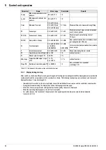
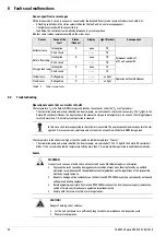
FlowSensor type

Value of

"FLS active" 

parameter

Minimum flow rate during 

start-up phase "V1" in l/min

Minimum flow rate during 

operating phase "V2" in l/min

Any

0

FLS deactivated - no flow quantity

FLS20 (

16 41 07)

20

2.0

1.5

FLS40 (

on request)

40

4.0

2.5

FLS100 (

16 41 03)

100*

10.0

5.5

Table  5-1 Overview of FlowSensors

*value set automatically when FlowSensor detected

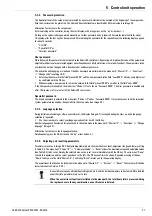
The calculation and balancing of the system's operating data (e. g. solar heat yield) are not substitutes for a 
calibrated calorimeter. These values may not be used for invoicing heating costs or similar legally valid account-
ing purposes.

An overall reset causes all individual settings to be lost and the incidence memory to be cleared. All calculated 
quantities (info parameters) are set to zero.

When the overall reset function is initiated via the menu path, the total heat yield is preserved. Using 
the rapid access via the key combination, even this value is deleted.

Summary of Contents for Solaris RPS3 25M

Page 1: ...t for large scale installations RPS3 25M Operating and installation manual Valid for the following components ROTEX SolarisRPS3 25M Solaris R3 temperature difference controller Sanicube Solaris and Hy...

Page 2: ...on contract procedures Exclusion of warranty Improper use tampering with system components pre assembled by ROTEXand improper modifications will immediately inval idate the guarantee Dispatch and tran...

Page 3: ...everalDHW storage tanks together 22 4 Commissioning and decommissioning 26 4 1 Commissioning 26 4 2 Decommissioning 28 4 2 1 Temporary shutdown 28 4 2 2 Permanent decommissioning 28 5 Control unit 29...

Page 4: ...heater burner inhibit contact 41 5 4 4 Tips for optimised user behaviour 41 5 4 5 Domestic water hygiene 42 6 Faults and malfunctions 43 6 1 Display of events 43 6 2 Troubleshooting 44 7 Hydraulic sy...

Page 5: ...on roof in roof and flat roof mounting ROTEX DHW storage tank Sanicube Solaris HybridCube GasSolarUnit GSU or HPSU compact Operating and installa tion instructions When connecting to an external heat...

Page 6: ...eplacement parts must at least satisfy the technical requirements defined by the manufacturer This is the case for example with original spare parts 1 5 Instructions for operating safety Working on th...

Page 7: ...Solaris flow layering pipe 15 Corrugated stainless steel heat exchanger for heating support 16 Thermal insulation of stainless steel heat exchanger for heating support 17 Solaris return connection wit...

Page 8: ...ROTEX Sanicube Solaris SCS thermally insulated unpressurised plastic storage tank with the facility to connect a ROTEX condensing boiler ROTEX HybridCube HYC thermally insulated unpressurised plastic...

Page 9: ...it RPS3 25M 16 41 11 Consists of 1 Cover 2 ROTEX Solaris R3 controller with storage tank temperature sensor return flow temperature sensor terminal connector for collector temperature sensor terminal...

Page 10: ...g the flow rate from 2 16 l min Consists of FlowGuard FLG a 2x seals b Illustration 2 4 FlowGuard FLG 16 42 32 For connecting a collector array V21P V26P H26P to the on site rigid copper connection pi...

Page 11: ...ater storage tanks in systems with up to 3 hot water storage tanks Consists of Return connecting pipe a Flow manifold b Illustration 2 8 CON SX optional 16 01 11 Extension kit for connecting a 3rd San...

Page 12: ...istance of the plastic connection pipes available from ROTEX is usually too high We recommend that you install connection lines made from rigid copper pipes on site 3 1 1 Parallel connection Illustrat...

Page 13: ...sure drop is calculated as the sum of the partial resistance values depending on the respective flow rates d Resistance of the feed and return connection pipes The pressure drop from the partial lines...

Page 14: ...total pressure drop and pump capacity WARNING Live parts can cause an electric shock on contact and cause life threatening burns and injuries Before beginning maintenance work on the boiler control pa...

Page 15: ...eplate on the wall 1 Unscrew the handle from the hot water storage tank 2 Unhook the controller from the housing baseplate by pulling in upward direction 3 Screw the housing baseplate loosely to the t...

Page 16: ...the desired side of the connecting T piece Illustration 3 10 Step 5 Illustration 3 11 Step 6 Illustration 3 12 Step 7 5 15mm 7 5mm x 6 7 A CAUTION When using plastic pipes in the case of longer horizo...

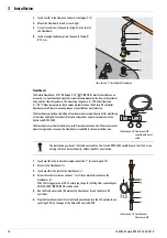
Page 17: ...9 Fit FlowGuard FLG 16 41 02 to the Solaris flow connection of the hot water storage tank see section 3 6 10 Fit push in fitting for flow connection from roof penetration kit RCAP RCRP RCIP RCFP or f...

Page 18: ...s heat ouput measurement via the Control unit RPS3 25M The FlowSensor must be installed in the solar flow line created on site Where several hot water storage tanks are used the FlowSensor is installe...

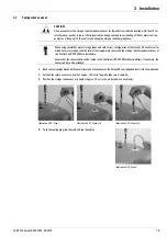
Page 19: ...et A sensor that is inserted too deeply can lead to overheating of the hot water section as well as a hang up of the control unit during the storage tank charging phase When using several hot water st...

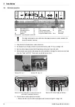
Page 20: ...baseplate from above Make sure that the loops in the cable are pointing downwards as shown in Image 3 27 to Image 3 28 BSK Burner inhibit contact CONF Programming socket for software update FLS FlowSe...

Page 21: ...l unit Permissible cable types on the terminal block Single wire 2 5 mm2 Multiwire 2 5 mm2 Multiwire with cable end sleeve with insulation collar 1 5 mm2 Multiwire with cable end sleeve without insula...

Page 22: ...32 To establish the return connection one CON RA 25M 16 01 13 connection set is required per hot water storage tank Additional equalising pipes must be connected to all hot water storage tanks connec...

Page 23: ...1 3 Hot water storage tank 2 Non pressurised area 3 Collector array 4 Circulation pump bottom and optional booster pump top 5 Solaris return flow connection pipe non pressurised area 6 Solaris flow ma...

Page 24: ...sor FLG FlowGuard RPS3 25M Control unit Illustration 3 33 Connecting several hot water storage tanks with flow manifold provided on site WARNING Danger of scalding after disconnecting the connection p...

Page 25: ...ions see chapter 2 1 Image 2 1 Pos 18 in a row 8 Install circulation pump and where applicable optional booster pump near the storage tank return connections Pumps piping and installation material mus...

Page 26: ...nal manner 6 Set the FlowGuard valves see also Table On systems without a booster pump set the flows in accordance with work step Chapter 3 2 System design Reference values for setting the flow rate d...

Page 27: ...lowGuard valves have been set the Sola ris system is subject to the maximum possible oper ating pressure A Work step A2 Work step with connected booster pump H Pressure boost through the pump H1 Deliv...

Page 28: ...ris installations are shut down temporarily the function protecting the pumps from seizing pump kick function is also disabled Check for correct pump function when starting up again Seized pumps can u...

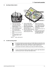
Page 29: ...r display down by one setting decreasing parameter settings 11 Information key for accessing the information level displays measured values maximum values and calculated values and OK key for confirmi...

Page 30: ...ff condition TV TR Delta T Off 2nd possibility Rapid switch off if the collector is cooling too quickly TK TR Delta T Off during the Filling time Time P2 parameter The maximum storage tank temperature...

Page 31: ...r It is active once after each 24 hour period of standstill The circulation pump and where installed the booster pump are switched on briefly for a few milliseconds thus pre venting pump seizure 5 2 5...

Page 32: ...g the current heat output and the solar heat yield The maximum and calculated values can be requested on the display see Chap 5 3 Values greater than 0 which have not been deleted are still displayed...

Page 33: ...error occurs three times in succession without the start phase minimum flow rate V1 being achieved the connected pump s switch es off permanently and the error message F appears in the left hand colum...

Page 34: ...2 5 Parameter Name Value range Resolution Remark TK max Max measured collector tem perature 30 to 250 C 1 K TK min Min measured collector tem perature 30 to 250 C 1 K V max Maximum flow rate 0 0 to 20...

Page 35: ...ut 1 second after a value has been changed In the selected parameter display pressing the OK key switches over to the parameter changing mode The first line of the menu Image 5 5 shows the active menu...

Page 36: ...5 x Control unit operation 36 FA ROTEX Solaris RPS3 25M 03 2010 Illustration 5 5 Setup menu...

Page 37: ...10 minutes or after a restart of the Solaris R3 control unit Specialist password The Expert password is entered in the menu item Choice 1 2 under Password 0000 It provides access to all the important...

Page 38: ...ture TS min is exceeded or if the preset minimum instantaneous output for burner stop P min is exceeded the burner inhibit contact only switches off after the set delay time has elapsed see Image 5 6...

Page 39: ...rating col lector temp 90 to 250 C 95 C 1 K TR min Minimum return temperature 10 to 60 C 25 C 1 K T frost Limiting collector temperature for activating the frost protec tion function 0 to 10 C 0 C 1 K...

Page 40: ...f the Solaris system System switch on involving steam generation can often be disconcerting for the operator The switch on inhibit temperature TK perm is preset at the factory to prevent boiling noise...

Page 41: ...of heat or the storage tank has reached a sufficiently high temperature 5 4 4 Tips for optimised user behaviour Hot water needs and user behaviour are highly individual The higher the desired storage...

Page 42: ...sed for several days and the storage tank temperature of the Solaris system does not reach at least 60 C we recommend that for reasons of hygiene legionella protection the stored water should be heate...

Page 43: ...off of P1 and optional P2 6 Supply Internal supply voltage fault G 7 Reference Internal reference voltage fault G 8 Reset Overall reset was carried out Parameters set to default values calculated valu...

Page 44: ...peration is enabled automatically Faults Sensor Cause of the fault Status flashes Display Light flashes Consequence Collector temp Interruption K uuuu TK Permanent switch off of P1 and optional P2 Sho...

Page 45: ...an empty in the circulation pump and where installed in the booster pump Check the pump s for air 2 Check the installation for leaks Check the installation for leaks and rectify if necessary Observe t...

Page 46: ...e fitted with plastic non return valves 16 50 70 These are suitable for operating temperatures up to 95 C If a heat exchanger is to be operated above 95 C the customer must install a different non ret...

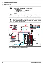
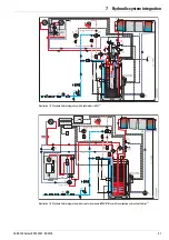
Page 47: ...47 FA ROTEX Solaris RPS3 25M 03 2010 Illustration 7 2 Standard Solaris integration with GasSolarUnit GSU 1 Illustration 7 3 Standard Solaris integration with air water heat pump HPSU Bi Bloc with roo...

Page 48: ...7 x Hydraulic system integration 48 FA ROTEX Solaris RPS3 25M 03 2010 Illustration 7 4 Solaris integration when using several Solaris storage tanks SCS large scale installations 1...

Page 49: ...7 x Hydraulic system integration 49 FA ROTEX Solaris RPS3 25M 03 2010 Illustration 7 5 Solaris integration with GSU cascade systems 1...

Page 50: ...agram showing Solaris integration in a large scale installation with 8000 l storage volume with 16 HYC hot water storage tanks Suitable for up to 156 m2 collector area 60 solar panels 1 1 The system s...

Page 51: ...or storage tank connections Accessories 16 50 70 8 Solar circuit 9 Fluid pipe for coolant circuit for HPSU Bi Bloc heat pump 10 Gas pipe for coolant circuit for HPSU Bi Bloc heat pump 11 Storage tank...

Page 52: ...only be used on a system by system basis RKHB Inside unit for HPSU Bi Bloc heat pump Supplied with HPSU heat pump RRHQ Outside unit for HPSU Bi Bloc heat pump RT Room thermostat Accessories 14 10 03 S...

Page 53: ...rs Solaris sensor Sensor type Measured temperature in C 20 10 0 10 20 30 40 50 60 70 80 90 100 110 120 Sensor resistance in Ohm according to standard or manufacturer s indications TR TS PTC 1386 1495...

Page 54: ...ROTEX condensing boilers heat pumps and hot water storage tanks can be found in the ROTEX price list and the corresponding technical documentation for the products a Collector array with connection f...

Page 55: ...ration 8 4 Hydraulic resistance of the flow connection on the hot water storage tank with FlowGuard valve fully opened CON RA 25M Return connection set with corrugated connecting pipe ball valve and p...

Page 56: ...Feed line ROTEX VA 15 Solar Q Flow rate in collector circuit P Pressure drop Illustration 8 6 Hydraulic resistance in ROTEX plastic connection pipes per metre Q Flow rate in collector circuit P Press...

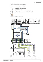
Page 57: ...r PCB BSK Burner inhibit contact CONF Programming socket for software update F1 Fuse FLS FlowSensor K1 Switching protection circulation pump K2 Switching protection booster pump L1 Phase mains connect...

Page 58: ...ce memory 32 37 43 Info parameters 32 34 35 37 Inhibit time 31 39 45 Installation Controller 20 FlowGuard 17 FlowSensor 17 Storage tank extension 24 Temperature sensor 19 Instantaneous output 34 L Lan...

Page 59: ...10 x Notes 59 FA ROTEX Solaris RPS3 25M 03 2010 10 Notes...

Page 60: ...FA ROTEX Solaris RPS3 25M 03 2010 x 008 1612144_00 Errors and technical changes excepted Original instructions 008 1612149_00 03 2010 in German ROTEX...

Reviews: