


11
DE
4.7. Concluding mechanical installation instructions
After the first start-up the correct alignment is to be checked while the
motor is as warm as it usually is while operating..
• All screws, nuts and other clamped or bolted connections
must be correctly assembled and fastened.
• The cooling air must be able to circulate without a problem.
4.8. Mounting the oil-sensor controller
If the optional available oil sensor controller (Order Nr. ZSP-
MOT00442) be included, assemble it as follows:
• Open the plug connection (A) between the float switch and the
main switch (ignition breaker), as well as the plug connection
(B) between main switch and ignition coil connector.
B
cable attached to ignition coil
cable attached to ignition coil
Oil float sensor
Oil sensor
controller
Oil float sensor
OFF
ON
A
F
OFF
ON
E
D
• Mount the oil sensor controller on the crankcase.
• Connect:
- Oil-sensor-controller and Oil-float-sensor (D)
- Oil-sensor-controller and Main switch (E)
- Main-switch and cable to ignition coil (F)
➽
How the oil sensor controller works:
By default the motor is equipped with a oil float sensor (=switch sen-
sor). When the oil level is too low, the float switch stops the motor. If
the float switch only triggers shortly the switch is not guaranteed to
successfully stop the engine. The oil sensor controller also stops the
motor when the oil level is only briefly too low.
4.9. Electrical Assembly (only for “E” version)
ATTENTION - By default engines in version "E" are delivered WITHOUT
stop-switch! The wiring MUST be adapted to one of the following.
Otherwise the running engine cannot be stopped.
Depending on the version the engine is equipped with following
electrical components:
➽
Version "H" (means only
H
and-start version):
No further electrical components
➽
Version "E" (means with additional
E
lectric-start):
Dynamo (without necessary diode) and electric starter.
ATTENTION: no stop-switch preinstalled!
➽
Special components (additionally available):
- Startbox (with rectifier diode and main-switch)
- Battery
4.9.1. Electrical connection (chords)
Only use stranded wire cable as a connection.
B) as well as battery(-) chords are to be held as short as
because the current of the starter is very high.
Note that the motor and add-on-parts get hot when used. Always
protect the cable from touching hot parts by using a protective hose.
Caused by motor vibration during operation all screw connections
must be secured with spring washers or lock-nuts.
4.9.2. Starter battery
A starter battery and a battery cable are not included in the delivery,
they can however be ordered separately as add-ons. Make note of
following points:
Lead acid batteries contain sulfuric acid. If there are liquids
escaping from the battery, do not touch or swallow them.
Carefully dilate the acid with water and neutralize it with soda
(sodium carbonate).
Always wear protective gloves and safety goggles when wor-
king with the starter battery.
• You can find the necessary capacities in the chart in chapter
3.1. The usage of valve-regulated (maintenance free) batteries
is recommended.
• Always connect the plus(+) pole first, then the minus(-) pole.
Fasten the connections properly.
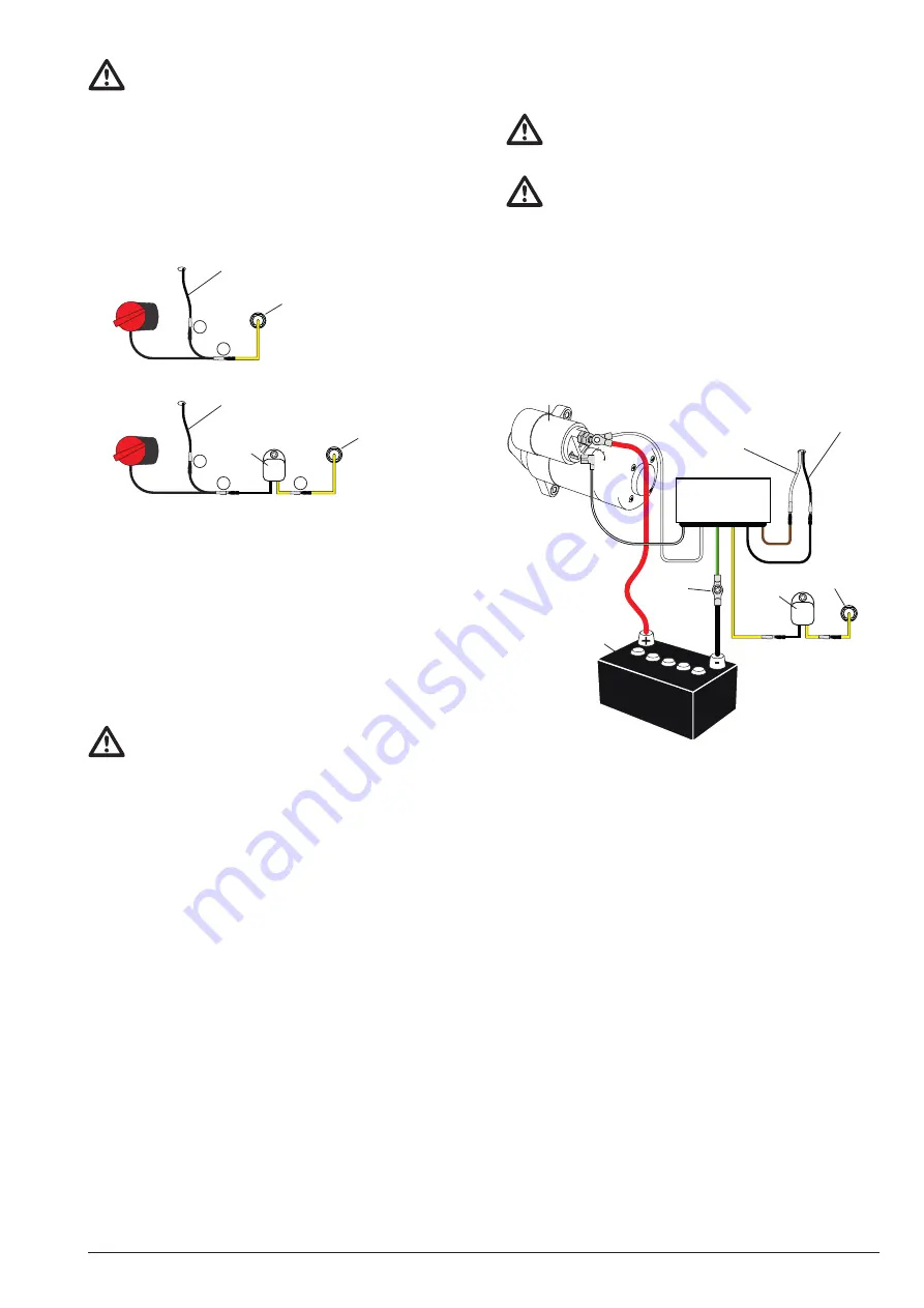
4.9.3. Mounting of optional Startbox
The optionally available starter box (with rectifier diode and main-
switch) is to be assembled as follows:
• Open all plug connections and assemble the starter box (see
pictures in 5.1.)
STARTBOX
Starter motor
Battery
Oil sensor
controller
CN30
CN11
CN10
CN2
CN3
CN6
GND
Crankcase
cable from dynamo
cable to
ignition coil
Oil sensor
• Mount a cable lug on both battery cables.
• Mount battery(-) cable as well as CN30 (yellow/green marked
cable with M6 cable lug) with any screw on the crankcase
(crankcase is allways ground/GND/0V).
• Connect CN2 (yellow marked cable with M4 cable lug) to oil-
sensor-controller (if no oil-sensor-controller is equipped con-
nect the cable with oil-sensor).
• Connect CN3 (black marked cable with M4 cable lug) to igniti-
on coil.
• Connect CN6 (brown marked cable with M4 cable lug) to dyna-
mo.
• Connect CN11 (black/white marked cable in heat protection
tube with 6,35mm Faston lug) to relais of starter motor.
• Connect b) cable with M6 cable lug to starter motor.
Connect CN10 (white marked cable in heat protection tube
with M6 cable lug) also to the same port of the starter motor.
• Secure all cables with the cable fixer und connect the battery
cables to the batteries - see notes under 4.9.2.


