


Expansions and Accessories
AuraSys™ L-2 and L-2K Installation Manual
27
Color coding in the Figure 15 may vary based on the installer’s wiring;
however, these are the standard color coding based on a typical
installation.
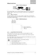
When connected as shown (and nothing is plugged into the jack), the
internal phones should work.
2.
Replace the cover on the jack.
The unit can now be connected to the security system.
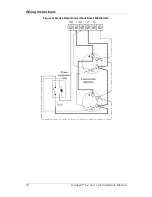
Figure 15: MD-31 to Alarm Panel Wiring
3.
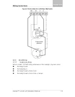
Connect the 50-cm cord to the alarm panel:
Yellow to "R" or "Ring" contact (Ring, from phone company)
Green to "T" or "Tip" contact (Tip, from phone company)
Brown to "R1" contact (Ring, To inside phones)
White to "T1" contact (Tip, to inside phones)
4.
Plug the 50-cm cord into the MD-31 and test communication.
B.2
SA-59 GSM Communicator
The SA-59 is a universal GSM reporting unit and communicator. When it is
connected to an alarm panel, the SA-59 operates as a GSM backup unit to the
PSTN line, enabling incoming and outgoing calls to be redirected to the GSM
network if the PSTN line fails. Since the SA-59 simulates a telephone line, it
makes no difference whether the device to which it is connected is a GSM or a
land line.
The built-in SA-59 GSM module connects via the PSTN line to check for phone
communication type availability. If there is no PSTN line, the SA-59
automatically switches the call from PSTN line to GSM.
When the SA-59 is connected to a telephone line (Line IN), the SA-59 tunnels
the device to a land line to make a call. If the land line is cut or not


