Wiring Instructions
AuraSys™ L-2 and L-2K Installation Manual
17
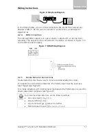
Figure 6: Telephone Diagram
In the United States, do not connect directly to the phone line; instead use
Rosslare’s MD-31 RJ-31X jack to connect to a phone line, as explained in
Appendix
A
.
4.2.4
PGM Connection
The onboard PGM output is an open-collector output with a 120 mA drive
capability. The output can be connected to the AUX+, as shown in Figure 7 or
to an external power supply.
Figure 7: PGM Wiring Diagram
4.2.5
Smoke Detector Connections
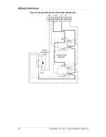
Smoke detectors that have a 2-wire input are wired exactly like zones.
To support four-wire smoke detectors, the PGM output must be used as a
reset trigger (see Figure 8).
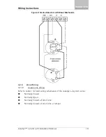
For smoke detectors with internal reset mechanism the PGM output is used for
power supervision purposes (see Figure 9).
For 4-wire fire/smoke detectors, use the following settings:
•
Zone input type
Single N.O.
•
Attached PGM
PGM 1
•
Zone Functional Type
24
-Hour Fire 4-Wires
•
PGM Activation Trigger
Fire Detector Control
LINE PHONE


