background image

Installation and Wiring 

AuraSys™ L-2 and L-2K Installation Manual 

13 

3.2.3


Mounting the Control Panel 

The L-2 control panel family comes in two enclosed versions: 


L-2 – Plastic enclosure with 2-state key switch 


L-2K – Plastic enclosure with 6-button arming keypad 

Follow the below instruction to mount the L-2 control panel family. 

To mount the L-2 and L-2K panel: 

1.


Using a Philips head screwdriver, unscrew the enclosure screws and open 

the L-2/2K enclosure. 

2.


Use the mounting template as shown in Figure 3 to drill holes in the wall. 

3.


Insert masonry anchors into the drilled holes. 

4.


Remove the PCB from the enclosure by gently pressing the PCB clasps to 

release the PCB from the enclosure. 

5.


Use a flat head screwdriver to gently remove the plastic knockouts of both 
the wiring hole and screw placement. 


The bottom left mounting location is required for the back tamper protection, 

and is the only hole without a knockout. 

6.


Thread the wires through the wiring hole and wire the unit as explained 
ahead in Chapter 


4. 

7.


Secure the L-2/2K panel to the wall using the supplied mounting screws. 


The tamper screw is different from the mounting screws. The mounting screws 

are pan head screws while the tamper screw is a unique flat head screw. 

8.


Place the PCB back into the back case of the enclosure; ensure that the 

claps are holding the PCB in place. 

9.


Close and secure the enclosure using a Philips head screwdriver. 

Summary of Contents for AuraSys L-2

Page 1: ...AuraSys L 2 2 4 Zone Alarm Access Panel Hardware Installation Manual Models L 2 L 2K ...

Page 2: ...al property rights covering the subject matter in this manual TEXTS IMAGES AND ILLUSTRATIONS INCLUDING THEIR ARRANGEMENT IN THIS DOCUMENT ARE SUBJECT TO THE PROTECTION OF COPYRIGHT LAWS AND OTHER LEGAL RIGHTS WORLDWIDE THEIR USE REPRODUCTION AND TRANSMITTAL TO THIRD PARTIES WITHOUT EXPRESS WRITTEN PERMISSION MAY RESULT IN LEGAL PROCEEDINGS The furnishing of this manual to any party does not give t...

Page 3: ...rol Panel 13 4 Wiring Instructions 15 4 1 Wiring Quick Reference 15 4 2 Wiring the System 16 4 2 1 AC DC Wiring 16 4 2 2 Battery Connection 16 4 2 3 Telephone Wiring 16 4 2 4 PGM Connection 17 4 2 5 Smoke Detector Connections 17 4 2 6 Zone Wiring 19 4 2 7 Sounder Connections 23 4 3 Preliminary Testing 23 5 Programming 24 5 1 Connections 24 5 2 Programming Options 24 A Battery Load Capacity 25 B Ex...

Page 4: ...Table of Contents iv AuraSys L 2 and L 2K Installation Manual D 1 Customer Information 31 D 2 Installer Information 31 D 3 Device Information 31 D 4 Zone Worksheet 32 E Limited Warranty 33 ...

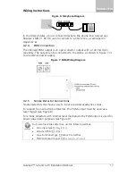
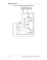
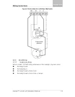
Page 5: ...ction Diagram 16 Figure 6 Telephone Diagram 17 Figure 7 PGM Wiring Diagram 17 Figure 8 Smoke Detectors without Reset Mechanism 18 Figure 9 Smoke Detectors with Reset Mechanism 19 Figure 10 Resistors 22 Figure 11 Sounder bell Connections 23 Figure 12 Rosslare s MD 62 TTL to RS 232 Converter 24 Figure 13 MD 31 Dimensions 26 Figure 14 MD 31 Internal Wiring 26 Figure 15 MD 31 to Alarm Panel Wiring 27 ...

Page 6: ... 20 Table 2 Hardwiring Schematics for Doubled Zone System 21 Table 3 Resistor Color Scheme 22 Table 4 Resistors Provided 22 Table 5 Battery Load Capacity 25 Table 6 Event Codes Contact ID and SIA Burglary and Fire 29 Table 7 Event Codes Contact ID and SIA Arming Events 29 Table 8 Event Codes Contact ID and SIA System Events 29 ...

Page 7: ...re options Therefore not all functions described in this manual may be available in the specific system and or product configuration you purchased Incorrect operation or installation or failure of the user to effectively maintain the system relieves the manufacturer and seller from all or any responsibility for consequent noncompliance damage or injury The text images and graphics contained in the...

Page 8: ...K 2 4 zone security system is a compact and advanced 2 zone doubled hardwired control panel for residential and light commercial intrusion alarms There are currently two versions of the L 2 product L 2 Away disarm using key switch L 2K Local arming using numeric keypad Figure 1 L 2 Control Panel ...

Page 9: ...Introduction AuraSys L 2 and L 2K Installation Manual 9 Figure 2 L 2K Control Panel ...

Page 10: ...er Protection Back and Front Cover Zone doubling Yes Max supported zones 4 Onboard PGM output 1 x OC 120 mA Sounder output 1 x 1 Ampere Onboard AUX output 12 VDC 1 0 Ampere User codes 6 in L 2K Non volatile event log size 256 Central station accounts primary secondary backup Yes Private telephone numbers Yes 3 Electrical Characteristics Power Supply Type Linear type recommended Input Voltage 16 VA...

Page 11: ...ironmental Characteristics Operating Environment Indoor use only Operating Temperature Range 15ºC to 44 C 5ºF to 111 2 F Operating Humidity Range 0 to 95 non condensing RFI Protection 20 V m up to 1000 MHz Supervision Tamper proof system with constant supervision Mechanical Specifications Dimensions Height x Width x Depth 130 x 170 x 38 mm 5 1 x 6 7 x 1 5 in Weight without battery 250 g 8 8 oz ...

Page 12: ...the individual manuals supplied with the detector 3 2 1 Preparing the Installation Environment Establish the control panel location using the following guidelines Locate the control panel in a place where the temperature is within the specified limits for operation When distributing wiring avoid putting the system wires close to house wiring to reduce capacitive coupling of noise Locate the contro...

Page 13: ...he enclosure by gently pressing the PCB clasps to release the PCB from the enclosure 5 Use a flat head screwdriver to gently remove the plastic knockouts of both the wiring hole and screw placement The bottom left mounting location is required for the back tamper protection and is the only hole without a knockout 6 Thread the wires through the wiring hole and wire the unit as explained ahead in Ch...

Page 14: ...Installation and Wiring 14 AuraSys L 2 and L 2K Installation Manual Figure 3 L 2 2K Mounting Template ...

Page 15: ... from the control panel PCB to other panel components are shown below Figure 4 L 2 2K Control Panel Components Connector Function BAT BT 05 16 battery connector VIN AC DC Power input for AC DC Voltage Bell Bell Siren connection PGM Programmable open collector output AUX 12 VDC power supply for external devices Z1 Z2 Zones 1 and 2 input connections Common ground Line Tip and Ring connection for pho...

Page 16: ... limited up to 1 2 A Refer to Chapter 2 for detailed electrical characteristics of the transformer 4 2 2 Battery Connection To connect the battery to the panel 1 Place the battery in the battery housing within the enclosure 2 Connect the battery s plug to the dedicated battery power jack on the PCB Figure 5 Battery Connection Diagram See Chapter 2 for detailed battery related information RISK OF F...

Page 17: ...shown in Figure 7 or to an external power supply Figure 7 PGM Wiring Diagram 4 2 5 Smoke Detector Connections Smoke detectors that have a 2 wire input are wired exactly like zones To support four wire smoke detectors the PGM output must be used as a reset trigger see Figure 8 For smoke detectors with internal reset mechanism the PGM output is used for power supervision purposes see Figure 9 For 4 ...

Page 18: ...Wiring Instructions 18 AuraSys L 2 and L 2K Installation Manual Figure 8 Smoke Detectors without Reset Mechanism ...

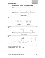
Page 19: ...19 Figure 9 Smoke Detectors with Reset Mechanism 4 2 6 Zone Wiring 4 2 6 1 Single Zone Wiring Refer to Table 1 for hard wiring schematics of the AuraSys L 2 system zones Normally Closed Normally Open Normally Closed End of Line Normally Closed End of Line Tamper ...

Page 20: ...hematics for Single Zone System 4 2 6 2 Zone Doubling Refer to Table 2 for hard wiring schematics of the AuraSys L 2 system for doubled zones Doubled Zone Normally Closed Doubled Zone Normally Open Doubled Zone Normally Closed End of Line Doubled Zone Normally Closed End of Line Tamper ...

Page 21: ...tallation Manual 21 Table 2 Hardwiring Schematics for Doubled Zone System 4 2 6 3 Resistors The AuraSys L 2 2K comes with 3 resistors for the various zones connections including tamper and EOL detection The resistors are 2 2 KΩ 4 7 KΩ and 8 2 KΩ ...

Page 22: ... represents the tolerance All resistors provided by Rosslare have a 5 tolerance represented by the color Gold To read the resistor number hold the unit with the gold stripe on the right The color scheme is as follows Table 3 Resistor Color Scheme Black 0 Brown 1 Red 2 Orange 3 Yellow 4 Green 5 Blue 6 Violet 7 Grey 8 White 9 Based on the above color scheme the resistors provided are as follows Tabl...

Page 23: ...ysically check the panel to ensure that there are no shorted or open connections 2 Power up the system All LEDs flash in sequence 3 Verify that all LEDs were lit After programming the system as explained in Chapter 5 perform the following preliminary tests 1 Perform a walk test for each of the zones 2 Verify that the corresponding LEDs are lit 3 Arm disarm the system to verify that the system beha...

Page 24: ...ial port Figure 12 Rosslare s MD 62 TTL to RS 232 Converter If your computer does not have a serial port use Rosslare s MD C24 USB to RS 232 converter 2 Connect the RS 232 connector to the PC 3 Ensure that the red wire in the cable s 10 pin connector is connected to Pin Number 1 on the PCB male connector 4 Run the AuraSys Lite Remote Programmer PC software To connect the AuraSys L 2 panel to the P...

Page 25: ...ad Capacity BT 05 800mAh BT 16 2 Ah Standby Current Maximum Current Standby Current Maximum Current L 2 Low 1 x PIRs 10 Hours 3 2 Hours 25 Hours 8 0 Hours L 2K Low 1 x PIRs 10 Hours 3 2 Hours 25 Hours 8 0 Hours L 2 Full 2 x PIRs 8 8 Hours 3 1 Hours 22 2 Hours 7 8 Hours L 2K Full 2 x PIRs 8 8 Hours 3 1 Hours 22 2 Hours 7 8 Hours ...

Page 26: ...e lines T1 and R1 The MD 31 has eight screw terminals inside the housing This makes it easy to connect the outside and inside lines To connect the MD 31 1 Connect the lines as shown in Figure 13 and Figure 14 The outside and inside lines can come into the jack from within the wall behind the jack or into either or both sides of the jack Figure 13 MD 31 Dimensions Figure 14 MD 31 Internal Wiring Ou...

Page 27: ...ct Tip to inside phones 4 Plug the 50 cm cord into the MD 31 and test communication B 2 SA 59 GSM Communicator The SA 59 is a universal GSM reporting unit and communicator When it is connected to an alarm panel the SA 59 operates as a GSM backup unit to the PSTN line enabling incoming and outgoing calls to be redirected to the GSM network if the PSTN line fails Since the SA 59 simulates a telephon...

Page 28: ...tallation Manual functioning all communications go via the GSM network without the need for any special additional settings If the SA 59 is not connected to a land line all communications take place via the GSM network Figure 16 Universal GSM Communicator ...

Page 29: ...0 Alarm 24 hour Silent Event E122 RF Supervisor Event E381 Alarm 24 hour Silent Restore R122 RF Supervisor Restore R381 Burglary Event E130 RF Tamper Event E383 Burglary Restore R130 RF Tamper Restore R383 Alarm 24 hour Audible Event E133 RF Low battery Event E384 Alarm 24 hour Audible Restore R133 RF Low battery Restore R384 Open Event E141 Table 7 Event Codes Contact ID and SIA Arming Events Arm...

Page 30: ...ell Over Event E312 Aux Bell Over Restore R312 REM Module Missing Event E330 REM Module Missing Restore R330 RF Jamming Event E344 RF Jamming Restore R344 Communication Fail Event E354 Communication Fail Restore R354 Swinger Over E377 Zone Bypass E570 Zone Un bypass R570 Fire Zone Bypass E571 Fire Zone Un bypass R571 CMS Test E602 Listen In Start E606 Inaccurate Time Event E626 Inaccurate Time Res...

Page 31: ..._____________________________________________________________ ___________________________________________________________________ Telephone ______________________ Installation Date ____________________ D 2 Installer Information Name _____________________________________________________________ Address ___________________________________________________________ _____________________________________...

Page 32: ...Worksheet Print out this Zone Worksheet and use it to plan programming values for each zone Zone Input Type Partition PGM Crossing Paired Zone Response time in100 ms Chime Alarm Verification PGM Activation on Zone Violation No Activity Monitoring Zone Crossing Walkthrough 01 02 03 04 ...

Page 33: ... Limited Warranty The full ROSSLARE Limited Warranty Statement is available in the Quick Links section on the ROSSLARE website at www rosslaresecurity com Rosslare considers any use of this product as agreement to the Warranty Terms even if you do not review them ...

Page 34: ...5 0069 support na rosslaresecurity com Europe Rosslare Israel Ltd Rosh HaAyin Israel Tel 972 3 938 6838 Fax 972 3 938 6830 support eu rosslaresecurity com Latin America Rosslare Latin America Buenos Aires Argentina Tel 54 11 4001 3104 support la rosslaresecurity com China Rosslare Electronics Shenzhen Ltd Shenzhen China Tel 86 755 8610 6842 Fax 86 755 8610 6101 support cn rosslaresecurity com Indi...

Reviews: