2013 March
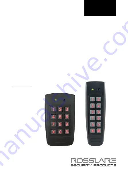
AC-F/G4x Family
Outdoor Backlit
Standalone Controllers
Installation and Programming Manual
Models:
AC-F43
AC-F44 AC-G43
AC-G44
AC-F4x
AC-G4x
Page 1: ...2013 March AC F G4x Family Outdoor Backlit Standalone Controllers Installation and Programming Manual Models AC F43 AC F44 AC G43 AC G44 AC F4x AC G4x ...
Page 2: ...erty rights covering the subject matter in this manual TEXTS IMAGES AND ILLUSTRATIONS INCLUDING THEIR ARRANGEMENT IN THIS DOCUMENT ARE SUBJECT TO THE PROTECTION OF COPYRIGHT LAWS AND OTHER LEGAL RIGHTS WORLDWIDE THEIR USE REPRODUCTION AND TRANSMITTAL TO THIRD PARTIES WITHOUT EXPRESS WRITTEN PERMISSION MAY RESULT IN LEGAL PROCEEDINGS The furnishing of this manual to any party does not give that par...
Page 3: ...lation 14 3 1 Mounting the Controller 14 3 2 Wiring the Controller 15 4 Operation 19 4 1 Modes of Operation 19 4 1 1 Normal Mode Default 19 4 1 2 Secure Mode 19 4 1 3 Bypass Mode 19 4 2 User Levels 20 4 3 Switching Operational Modes 21 4 3 1 From Normal to Secure Mode 21 4 3 2 From Secure to Normal Mode 21 4 3 3 From Normal to Bypass Mode 22 4 3 4 From Bypass to Normal Mode 22 4 4 Special Operatio...
Page 4: ...ode 30 5 6 Changing the Normal Bypass Code 31 5 7 Setting Fail Safe Secure Operation 32 5 8 Setting Auxiliary Modes 33 5 8 1 General 33 5 8 2 Detailed Reference Guide 36 5 9 Setting the Lockout Feature 40 5 10 Backlight and LED Behavior 41 5 11 Enrolling Codes 42 5 11 1 Primary Codes Definition 42 5 11 2 Secondary Codes Definition 42 5 11 3 Primary and Secondary Codes Enrolling Methods 42 5 11 4 S...
Page 5: ...ual v 5 13 1 Relay Code Assignment using Standard Method 47 5 13 2 Relay Code Assignment using Search Method 48 5 14 Changing PIN Code Length Factory Default Settings 49 5 15 Replacing a Programming Code 50 5 16 Replacing a Normal Secure Code 50 A Limited Warranty 51 ...
Page 6: ...Figure 1 Front Panel of AC F4x Series 11 Figure 2 Front Panel of AC G4x Series 12 Figure 3 Drilling Holes Identification 14 Figure 4 Wiring Diagram for Lock Strike Relay REX 16 Figure 5 Wiring Diagram for Auxiliary Input Output 17 Figure 6 Wiring Diagram for the BL D40 External Sounder 18 ...
Page 7: ...ist of Tables AC F G4x Family Installation and Programming Manual vii List of Tables Table 1 Wiring Color Guide 15 Table 2 Programming Menus 26 Table 3 Quick Reference Guide for Auxiliary Mode Setting 35 ...
Page 8: ...um configuration of the system with the maximum number of functions including future options Therefore not all functions described in this manual may be available in the specific system and or product configuration you purchased Incorrect operation or installation or failure of the user to effectively maintain the system relieves the manufacturer and seller from all or any responsibility for conse...
Page 9: ...er Types The different types of control units described in this manual are AC F43 PIN only AC F44 PIN and proximity card AC G43 Mullion Box PIN only AC G44 Mullion Box PIN and proximity card Relay Current Backlight Keypad Type Proximity AC F43 2 A 3X4 Standard AC F44 2 A 3X4 Standard AC G43 2 A 2X6 Mullion AC G44 2 A 2X6 Mullion 1 2 Key Features 500 users Water resistant Programmable Backlight and...
Page 10: ...dicators for status programming Interface Built in case and back tamper protection Lockout feature on wrong entries Keypad Card Tamper Bell chime siren and strobe features available with BL D40 Programmable siren time with BL D40 Programmable lock strike release time Supplied with mounting template for easy installation 1 3 Box Content Before beginning verify that all of the following is in the bo...
Page 11: ... regulated power supply or 16 to 24 VAC from a transformer Request to Exit REX Button optional normally open type switch is closed when pressed BL D40 External Sounder optional provides siren bell and chime Magnetic contact optional installed for door monitor capabilities Other Rosslare accessories can be found at Rosslare s Website www rosslaresecurity com 1 5 10BFront Panel Description Figure 1 ...
Page 12: ...Introduction 12 AC F G4x Family Installation and Programming Manual Figure 2 Front Panel of AC G4x Series ...
Page 13: ... Read Range N A 75 mm 2 95 in N A 80 mm 3 15 in Proximity Modulation N A ASK at125 KHz N A ASK at 125 KHz Proximity Card Compatibility N A 26 Bits EM cards N A 26 Bits EM cards LED Indicators Two 3 colored LED Mode and Door Operating Temperatures 22 F to 150 F 30 C to 65 C Operating Humidity 0 to 95 non condensing Outdoor Usage Weather resistant meets IP 65 Epoxy potted Size H x W x D 120 9 x 71 1...
Page 14: ...oles in the rear cover Figure 3 Figure 3 Drilling Holes Identification The central hole is for routing the wiring to the controller 3 Use the provided drilling template to accurately locate and drill the required holes in the wall or panel 4 Use the hardware provided to mount the back plate on the wall or on a gang box Be sure to route the wiring via the large center hole in the back plate Check f...
Page 15: ...to the corresponding ancillary devices and insulate each connection including unused wires 3 Refer to Table 1 and to the wiring diagrams depending on the desired application Wiring the Lock Strike Relay REX Figure 4 Wiring for Auxiliary Input Output Figure 5 Wiring for the BL D40 External Sounder Figure 6 Table 1 Wiring Color Guide Color Description Red V input Black Ground Green REX BL White In M...
Page 16: ...Installation 16 AC F G4x Family Installation and Programming Manual Figure 4 Wiring Diagram for Lock Strike Relay REX ...
Page 17: ...Installation AC F G4x Family Installation and Programming Manual 17 Figure 5 Wiring Diagram for Auxiliary Input Output ...
Page 18: ...Installation 18 AC F G4x Family Installation and Programming Manual Figure 6 Wiring Diagram for the BL D40 External Sounder ...
Page 19: ...ecure Mode The mode indicator is red Only secure and master users can access the premises in Secure mode A secure user must enter a primary and secondary code to gain entry Once the primary code has been entered the Door indicator flashes green for 10 seconds During this time the secondary code must be entered A master user only needs to enter his code to gain entry 4 1 3 Bypass Mode The mode indi...
Page 20: ...operation There are three user levels Normal User A normal user only has a primary code and is granted access only when the controller is in its Normal or Bypass mode Secure User A secure user must have a primary and secondary code assigned and the two codes must not be the same The secure user can gain access in any mode of operation In Normal mode the secure user must use the primary code to gai...
Page 21: ...ler can also be used to switch the mode of operation from secure to normal and vice versa if the auxiliary input is selected it de activates the Norma Secure mode code see Section 5 8 4 3 2 From Secure to Normal Mode The default factory setting for the normal secure code is 3838 To change from Secure to Normal mode 1 Enter the Normal Secure code The Mode indicator flashes green 2 Press to confirm ...
Page 22: ... the Normal Bypass code The Mode indicator flashes orange 2 Press to confirm the Mode change The Mode indicator turns orange 4 3 4 From Bypass to Normal Mode To change from Bypass to Normal mode 1 Enter the Normal Bypass code The Mode indicator flashes green 2 Press to confirm the Mode change The Mode indicator turns green 4 4 Special Operational Features Some installation specific features are ex...
Page 23: ...e REX pushbutton is pressed the door is unlocked until the Lock Strike Release time has elapsed After this time the door is locked even if the REX pushbutton has not been released Failsafe Operation From the moment the REX pushbutton is pressed the door is unlocked until the REX pushbutton is released In this case the Lock Strike relay only begins its countdown once the REX pushbutton is released ...
Page 24: ...remises The Sounder can be powered by a 12 to 24 VDC power supply or by a 16VAC transformer The BL D40 is capable of emitting four different types of audible and visual alerts bell chime siren and strobe light The bell sounds when the controller s bell button is pressed The door chime can be programmed to sound whenever a valid code is entered as well as for a door held open alert The siren can be...
Page 25: ...imity card is mentioned the meaning may vary between units 5 1 Introduction Programming an access control unit is done solely via the unit s keypad driven Programming Menu System To reach the Programming Menu System the controller must first be placed into Programming Mode see Section 5 1 1 During the manufacturing process certain codes and settings are pre programmed These settings are the called...
Page 26: ...ary code 0852 08520 085208 08520852 5 3 3 Change Program code 1234 12341 123412 12341234 5 4 4 Change Normal Secure code 3838 38383 383838 38383838 5 5 5 Change Normal Bypass code 5 6 6 Change Door Release time 0004 5 7 6 Define auxiliary inputs outputs 2004 5 8 6 Set Lockout Feature 4000 5 9 6 Backlight and LED Behavior 5100 5 10 7 Enroll proximity cards PIN or both 5 11 8 Delete proximity cards ...
Page 27: ...ogramming code is valid the door Indicator turns green and the controller enters the Programming mode 5 1 2 Exiting the Programming Mode Wrong entries may reset the controller back to Normal mode If no key is pressed for 1 minute while in programming mode the controller exits Programming mode and returns to Normal mode To exit Programming mode 1 Press twice within 0 5 seconds You hear three beeps ...
Page 28: ... code is automatically deleted non default codes are not be erased automatically Open code does not function in Secure mode For wrong entries you hear a long beep and the controller returns to Normal mode Code 0000 erases and deactivate the open code To change the Open code 1 Enter Programming mode 2 Press 1 to enter Menu 1 The Mode indicator turns red 3 Enter the new code you wish to set as open ...
Page 29: ...eleted non default codes are not be erased automatically Auxiliary code does not function in Secure mode Auxiliary code only works when the auxiliary mode is 0 1 8 or 9 Wrong entries You hear a long beep and the controller returns to Normal mode Code 0000 erases and deactivates the auxiliary code To change the Auxiliary code 1 Enter Programming mode 2 Press 2 to enter Menu 2 The Mode indicator tur...
Page 30: ...Mode indicator turns green 4 The system returns to Normal mode You hear three beeps The Door indicator turns off The Mode indicator turns green 5 5 Changing the Normal Secure Code When the auxiliary mode is 1 2 3 or 4 the auxiliary input takes priority over the Normal Secure code For wrong entries you hear a long beep and the controller returns to Normal mode Code 0000 erases and deactivates the n...
Page 31: ...hime is only heard when the Lock Strike relay is activated by a valid code entry Wrong entries You hear a long beep and the controller returns to Normal mode Code 0000 erases and deactivates the Normal Bypass code To change the Normal Bypass code 1 Enter Programming mode 2 Press 5 to enter Menu 5 The Mode indicator flashes orange There are four different ways to program the Normal Bypass code and ...
Page 32: ...ff The Mode indicator turns green 5 7 Setting Fail Safe Secure Operation In this paragraph the failsafe fail secure operation of the door lock and the Door Lock Strike Release time are set Setting the sounding period for the siren feature requires a BL D40 External Sounder To set the failsafe secure operation 1 Enter Programming mode 2 Press 6 to enter Menu 6 The Mode indicator flashes green 3 Con...
Page 33: ...e is to be released after the number of seconds entered 1 to 99 For example 0 5 1 2 means fail secure operation 0 with5 minutes Siren time 5 and a 12 second Lock Strike Release time 12 The system returns to Normal mode You hear three beeps The Door indicator turns off The Mode indicator turns green 5 8 Setting Auxiliary Modes 5 8 1 General The default auxiliary setting is 2004 To set Auxiliary mod...
Page 34: ...Mode In addition to the Lock Strike relay and the Lock Strike REX the controller features an auxiliary output relay and an auxiliary input whose function is established by the auxiliary mode selection 0 thru 9 The auxiliary mode also determines if the auxiliary output relay is set for failsafe or for fail secure operation For a more detailed explanation on each auxiliary mode see Table 3 below Aux...
Page 35: ...00 Aux relay toggle 2 Normal Secure switch Star button N O 01 to 99 Aux Relay Release Time 00 Aux relay toggle 3 Normal Secure switch Tamper event N C 01 to 99 Aux Relay Release Time 00 Aux relay tamper activated 4 Normal Secure switch Direct shunt N O 01 to 99 Shunt time 5 Door Monitor Shunt N C 01 to 99 maximum Shunt time 6 Door Monitor Forced door N C 01 to 99 Forced delay 7 Door Monitor Door a...
Page 36: ...put function Toggles Normal Secure modes Auxiliary output activated by Valid user code Auxiliary code For example in Auxiliary Mode 1 the controller can function as a two door controller The auxiliary relay is to be attached to the lock on the second door REX feature for the second door is not enabled when using this mode The auxiliary setting defines the Door Open time for the second door The aux...
Page 37: ...uring office hours to Secure mode after office hours 5 8 2 5 Auxiliary Mode 4 Auxiliary input function Toggles Normal Secure modes Auxiliary output activated by direct shunt explanation below For example in Auxiliary Mode 4 the controller is capable of bypassing an alarm zone by shunting an alarm system s door sensor The auxiliary output is to be wired in parallel to the door sensor output When in...
Page 38: ...em If the door is forced open the controller waits for the period of the Forced Door Delay time to elapse and then it activates the auxiliary relay The auxiliary setting sets the forced door delay period 5 8 2 8 Auxiliary Mode 7 Auxiliary input function Door Monitor Auxiliary output activated by Door Ajar door held open For example in Auxiliary Mode 7 the controller can trigger the auxiliary relay...
Page 39: ...he Door indicator LED The indicator LED is not lit when A valid code is entered While in Secure mode when waiting for a secondary code 5 8 2 10 Auxiliary Mode 9 Auxiliary input function Red LED control Auxiliary output activated by Valid user code Auxiliary code For example in Auxiliary Mode 9 the controller can function as a two door controller and also provide indicator functionality control The...
Page 40: ...ller beeps every two seconds The default setting for the Lockout Feature is 4000 Lockout Disabled Using the lockout feature is highly recommended especially when selecting to use short PIN code length 4 or 5 digits To define the Lockout feature 1 Enter Programming mode 2 Press 6 to enter Menu 6 The Mode indicator flashes green 3 Construct a code using the following instructions Set the number of w...
Page 41: ...mming mode 2 Press 6 to enter Menu 6 3 The Mode indicator flashes green 4 Construct a code using the following instructions The first digit is five indicating the backlight and Led option The second key can be 0 3 indicating the type of activity Option 0 LED Active Backlight Off Option 1 LED Active Backlight On default Option 2 LED and Backlight Off both activated on any key press for 10 seconds O...
Page 42: ... be unique for instance one user s Secondary code may be the same as that of another user Secondary codes cannot be the same as any system codes such as the normal secure code or the open code Users possessing secondary codes can gain entry in any mode of operation A Secondary code can be the same as the primary code of any user 5 11 3 Primary and Secondary Codes Enrolling Methods There are two me...
Page 43: ...slot 003 represents User No 3 4 There are three possibilities If the selected slot has no primary code the Mode indicator flashes green indicating that the controller is ready to accept a primary code If the selected slot already has a primary code but no secondary code the Mode indicator flashes red indicating that the controller is ready to accept a secondary code If the selected slot already ha...
Page 44: ...ode search method enables to quickly enroll a secondary code for a user whose primary code is known and whose slot number is unknown To enroll codes using the Search method 1 Enter Programming mode 2 Press 7 to enter Menu 7 The Door indicator turns orange 3 Enter the 3 digit user slot number 000 The Door indicator flashes orange The controller is now waiting for the primary code of the user 4 Ente...
Page 45: ...ser slot both the primary code and the secondary code are erased It is recommended that a record be kept of added and deleted users This makes it easier to keep track of user slots status empty or not 5 12 1 Standard Method for Deleting Codes 1 Enter Programming mode 2 Press 8 to enter Menu 8 The Mode indicator turns red The Door indicator turns orange 3 Enter the 3 digit user slot code to be dele...
Page 46: ...hes orange The controller is now waiting for the primary code of the user to be deleted 4 Enter the primary code to be deleted The Mode indicator flashes red 5 Enter your programming code to confirm the deletion If the programming code is valid three beeps are heard and the controller returns to Normal mode If the programming code is invalid a long beep is heard and the controller returns to Norma...
Page 47: ... The Door indicator turns orange 3 Enter the 3 digit user slot for code assignment The Mode indicator flashes green 4 Enter the assignment digit for the current user slot 1 activates the Lock Strike relay only deafult 2 activates the Auxiliary relay only 3 activates the Lock Strike and Auxiliary relays If the assignment code is valid the Mode indicator stops flashing The controller is now waiting ...
Page 48: ... code of the user 4 Enter the primary code belonging to the user The Mode indicator flashes green 5 Enter the assignment digit for the current user slot 1 activates the Lock Strike relay only deafult 2 activates the Auxiliary relay only 3 activates the Lock Strike and Auxiliary relays If the assignment digit is valid three beeps are heard and the controller returns to Normal mode If the assignment...
Page 49: ...s to factory defaults and sets a 5 digit code 06 Returns to factory defaults and sets a 6 digit code 08 Returns to factory defaults and sets a 4 8 digit code When choosing the 4 8 option please note that you should either enter zeros before the code or press pound at the end for example if your code is 12345 enter either 00012345 or 12345 Both the Mode and Door indicators flash red 3 Enter your Pr...
Page 50: ...fault code before the controller reverts to the existing code The deafult code depends on the PIN length selected see Table 2 5 16 Replacing a Normal Secure Code The controller must be in its Secure mode for the procedure to work Insure that the Mode indicator is red before proceeding To replace a Normal Secure code 1 Remove power from the controller 2 Press and hold the REX pushbutton 3 Apply pow...
Page 51: ...er with the price of the Product paid by Customer provided that the warranty claim is delivered to ROSSLARE by the Customer during the warranty period in accordance with the terms of this warranty Unless otherwise requested by a ROSSLARE representative return of the failed product s is not immediately required If ROSSLARE has not contacted the Customer within a sixty 60 day holding period followin...
Page 52: ...ght cost to the repair center removal or reinstallation of the product whether or not proven defective Specifically excluded from this warranty are any failures resulting from Customer s improper testing operation installation or damage resulting from use of the Product in other than its normal and customary manner or any maintenance modification alteration or adjustment or any type of abuse negle...
Page 53: ...on implied warranties of merchantability and fitness for a particular purpose are specifically excluded In no event shall ROSSLARE be liable for damages in excess of the purchase price of the product or for any other incidental consequential or special damages including but not limited to loss of use loss of time commercial loss inconvenience and loss of profits arising out of the installation use...
Page 54: ...69 support na rosslaresecurity com Europe Rosslare Israel Ltd Rosh HaAyin Israel Tel 972 3 938 6838 Fax 972 3 938 6830 support eu rosslaresecurity com Latin America Rosslare Latin America Buenos Aires Argentina support la rosslaresecurity com China Rosslare Electronics Shenzhen Ltd Shenzhen China Tel 86 755 8610 6842 Fax 86 755 8610 6101 support cn rosslaresecurity com India Rosslare Electronics I...