Ross Ultripower User Manual Download Page 16

16 • Physical Installation

Ultripower User Guide (v4.0)

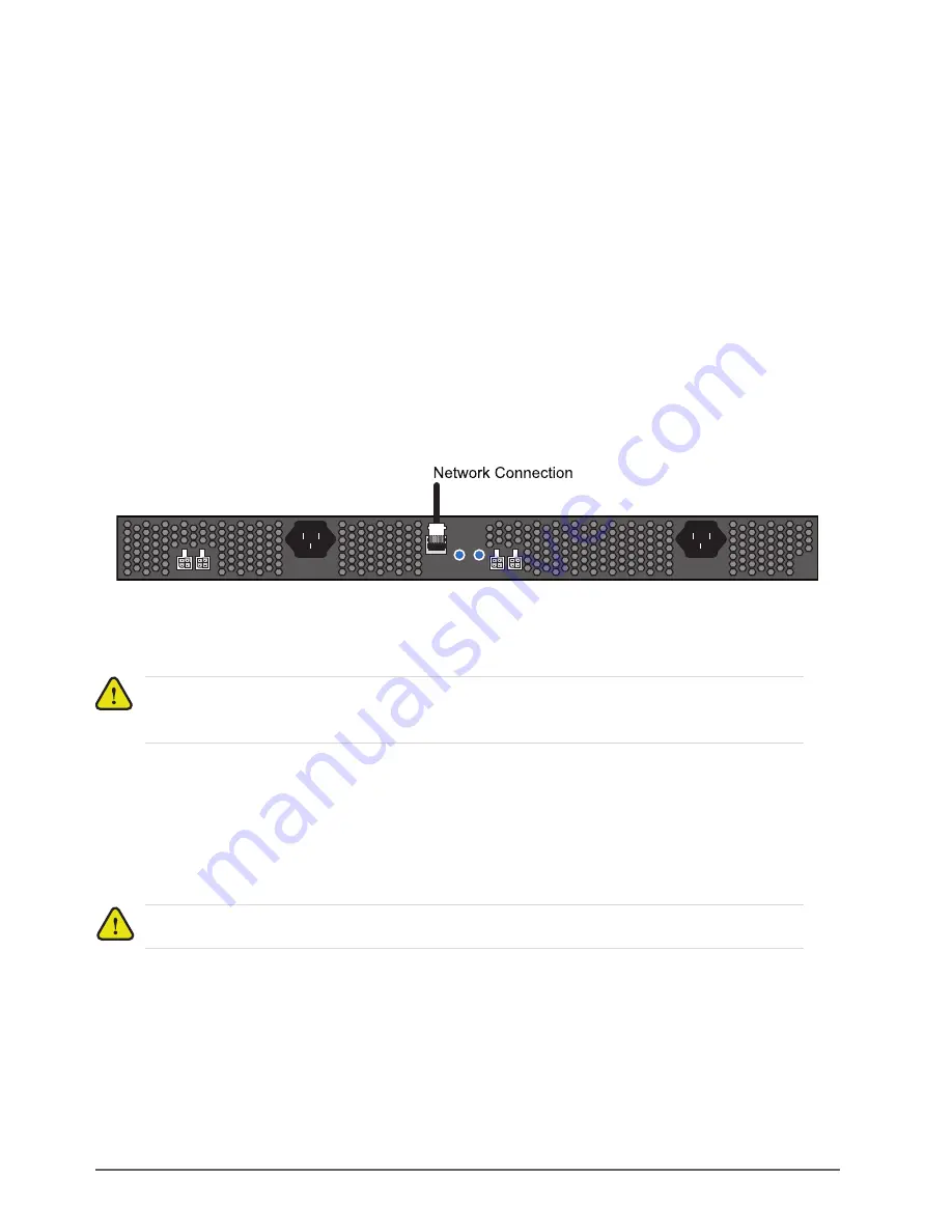
Connecting Ultripower to a Network

The 

ETHERNET

 port is a standard 10/100 RJ45 Ethernet connector and is used to exchange data and 

communicate with control and monitoring applications such as DashBoard. 

Contact your IT department before connecting to your facility network to ensure that there are no conflicts. They 
will provide you with an appropriate value for the IP Address, Subnet Mask, and Gateway for your device.

The Ultripower is connected directly to your network so that it can interface with the devices and the computer 
running the DashBoard client. After a physical connection is established, DashBoard is used to configure the 
network settings for the Ultripower.

For More Information on...

• downloading and installing DashBoard, refer to the 

DashBoard User Manual

.

If difficulties or problems are experienced when connecting the Ultripower to a network hub, or with assigning 
IP addresses, please contact your network administrator.

To establish a physical connection to the network

1. Connect one free end of a standard CAT 5/5e/6 Ethernet cable to a free port of the network hub.

2. Connect the other end of the same cable to the 

ETHERNET 

port on the rear of the Ultripower.

Figure 4.1  Ultripower — Network Connections

Connecting an Ultrix Router to Ultripower

You must first establish DC connections between the Ultrix routers and Ultripower before you can connect a power 
source to the Ultripower. 

Connecting to an ULTRIX-FR1 Router

You must use a Molex® connector on one end to connect to the Ultripower, and a Molex® connector on the other to 
connect to the Ultrix-FR1 router. This cable is supplied by Ross Video and shipped with Ultripower. 

Caution

 — Do not exceed 1200W total power for all connected devices. Damage can occur and the 

Ultripower will not be able to supply power if the limit is exceeded. Refer to the appropriate user guide for 
the maximum power consumption of each device, or contact Ross Video Technical Support.

Notice

 — The ULTRIX-FR1 router automatically powers on when power is applied to Ultripower.

1

2

OUT

2

1

OUT 

3

RESTART 

ETHERNET

RESET 

Summary of Contents for Ultripower

Page 1: ...Ultripower User Guide...

Page 2: ...eople that make things happen At Ross our employees are a special group Our employees truly care about doing a great job and delivering a high quality customer experience every day This code of ethics...

Page 3: ...manual Trademarks Google is a registered trademark of Google Inc Microsoft Excel and Internet Explorer are either registered trademarks or trademarks of Microsoft Corporation in the United States and...

Page 4: ...ular purpose are expressly limited to the duration of this warranty This warranty is TRANSFERABLE to subsequent owners subject to Ross notification of change of ownership Environmental Information The...

Page 5: ...O Box 880 Ogdensburg New York USA 13669 0880 General Business Office 1 613 652 4886 Fax 1 613 652 4425 Technical Support 1 613 652 4886 After Hours Emergency 1 613 349 0006 E mail Technical Support t...

Page 6: ......

Page 7: ...ork 16 Connecting an Ultrix Router to Ultripower 16 Connecting to an ULTRIX FR1 Router 16 Connecting to an ULTRIX FR2 Router 17 Connecting to an ULTRIX FR5 Router 18 Connecting to a Power Source 19 Co...

Page 8: ...Control Tab 30 Log Tab 31 Setup Tab 31 Network Tab 32 Maintenance 33 Installing a PSU Module 33 Removing a Blank Module Plate from the Ultripower Chassis 33 Removing the PSU Module from the Ultripowe...

Page 9: ...e from the chassis removing a PSU module from the chassis and installing a new PSU module Technical Specifications provides the specifications such as dimensions and power consumption for the Ultripow...

Page 10: ...s Video we take pride in the quality of our products but if problems occur help is as close as the nearest telephone Our 24 hour Hot Line service ensures you have access to technical expertise around...

Page 11: ...d as a positive power rail supply Supported Devices The Ultripower supports the following Ross devices ULTRIX FR1 ULTRIX FR2 ULTRIX FR5 Features The Ultripower includes the following features 1200W ou...

Page 12: ...1 1 4 A B REF 1 2 3 4 5 6 7 8 9 10 11 12 13 14 15 16 1 2 3 4 5 6 7 8 9 10 11 12 13 14 15 16 AUX A AUX B OUT IN 1 2 3 4 5 6 7 8 9 10 11 12 13 14 15 16 1 2 3 4 5 6 7 8 9 10 11 12 13 14 15 16 AUX A AUX B...

Page 13: ...3 Slot 2 Power Supply Module The Slot 2 Power Supply Module provides power to the four DC outputs If a PSU module is present and operating in Slot 1 the load is distributed between the operating modu...

Page 14: ...10 00 Ethernet Port The Ethernet port is an RJ45 connector used to connect the Ultripower to an external Ethernet network This port is required for monitoring and control of Ultripower 4 Reset and Res...

Page 15: ...in the correct warranty service procedures We recommend that the equipment is installed by qualified and experience personnel to any relevant standards and approvals Mounting Requirements The Ultripow...

Page 16: ...tact your network administrator To establish a physical connection to the network 1 Connect one free end of a standard CAT 5 5e 6 Ethernet cable to a free port of the network hub 2 Connect the other e...

Page 17: ...e end with the ferrite bead connects to the Ultripower port Figure 4 2 Notice The ULTRIX FR2 requires a minimum of two power supply connections Notice Ensure that the power cable end with the ferrite...

Page 18: ...ct an AC power cable to the Ultripower PSU 1 socket 4 If Ultripower is fitted with a second power module connect a second AC power cable to the Ultripower PSU 2 socket Notice The ULTRIX FR2 router aut...

Page 19: ...supply cord Use only certified cords for the country of use REF 1 2 3 4 5 6 7 8 9 10 11 12 13 14 15 16 1 2 3 4 5 6 7 8 9 10 11 12 13 14 15 OUT IN 1 2 3 4 5 6 7 8 9 10 11 12 13 14 15 16 1 2 3 4 5 6 7...

Page 20: ...the socket marked A on the Ultripower rear panel Figure 4 5 Ultripower Power Connections 2 Connect the remaining power cable into the socket marked B 3 Connect the supplied AC power cable into the po...

Page 21: ...ct File Show Walkabout The DashBoard window displays the Walkabout table 3 Click Refresh located at the bottom of the Walkabout tab to ensure the list in the Walkabout interface is current 4 In the Wa...

Page 22: ...ess field that you assigned in the section To assign the initial static IP address for the Ultripower on page 21 7 Perform one of the following steps In the text fields provided enter the display name...

Page 23: ...ss the Ultripower To add a DashBoard client to the Ultripower DB Whitelist 1 Display the Ultripower interface in DashBoard as outlined in the procedure To access the Database interfaces in DashBoard o...

Page 24: ...el to a physical Output Port on the Ultripower chassis Some external devices require multiple ports e g ULTRIX FR5 requires four ports Refer to the user guide for your external device to confirm the n...

Page 25: ...Ultripower User Guide v4 0 Configuration 25 7 Click Yes The Confirm dialog closes and power is enabled to that device...

Page 26: ...26 Configuration Ultripower User Guide v4 0...

Page 27: ...Monitoring via the Rear Panel LEDs The Ultripower rear panel includes LEDs on the ETHERNET RJ45 port Figure 6 1 Figure 6 1 ETHERNET Port LEDs Table 6 1 Front Panel Power Supply Module LEDs LED Status...

Page 28: ...ect the Alarm on missing PSU check box To view the status of a PSU slot via DashBoard 1 Locate the Ultripower in the Tree View of DashBoard 2 Expand the Ultripower node 3 Double click the Ultripower s...

Page 29: ...orts the most severe alarm for a single field Alarm colors are noted within the tables as text set in brackets next to the menu parameter name Product Tab Table 7 1 summarizes the read only informatio...

Page 30: ...area network LAN Active Connections Indicates the total number of active DashBoard client connections to this unit Table 7 3 PSU Tab Item Parameters Description PSU Slot Status OK Green Ultripower is...

Page 31: ...the device power state Table 7 5 Log Tab Message Description Outx overcurrenta a Where x is output 1 to 4 the device connected to output port x is drawing too much current Outx undervoltage the outpu...

Page 32: ...name to the device This name also displays in the DashBoard tree view The default is Ultripower IP Address Specifies the IP address for the Ultripower The default is 192 168 20 123 Subnet Mask Specifi...

Page 33: ...er Chassis on page 34 Removing the PSU Module from the Ultripower Chassis Each PSU Module is accessed via the front of the Ultripower chassis and requires that you loosen the two retaining bolts secur...

Page 34: ...following procedure is applicable to any PSU Module slot To install a new PSU module into the chassis 1 Align the new PSU module into the slot inside the chassis 2 Gently slide the new PSU module into...

Page 35: ...nvironmental Table 9 1 Physical Dimensions Item Specifications Width not including rack mounting ears 17 5 444 5mm Depth chassis only 8 1 206mm Height 1 7 43 2mm Weight approx Chassis 1PSU 3 24kg 7 14...

Page 36: ...36 Technical Specifications Ultripower User Guide v4 0...

Reviews: