OGX-FR Series User Guide (v1.0)
Ethernet Cabling • 21
Ethernet Cabling
The exact steps for connecting to your facility via an ethernet network depends on the network requirements of your
facility. Contact your IT Department before connecting to your facility network to ensure that there are no conflicts.
DashBoard uses the open SLP protocol to locate openGear frames on the network.
For More Information on...
• configuring the Network Controller card, refer to its user guide.
• installing and using DashBoard, refer to the
DashBoard User Manual
.
• the specifications for the OGX-FR, refer to the chapter “
Cabling the Ethernet Port on the OGX-FR Frame
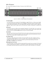
The Ethernet port is a standard 10/100/1000 RJ45 Ethernet connector and is used to exchange information with an
external monitoring, or control, system over an ethernet network. You must have the MFC-OG3-N installed in the
OGX-FR to take advantage of the Gigabit ethernet connectivity available for cards in the OGX-FR frame.
Required Pinouts
The Ethernet port has its RJ45 connector wired as a Network Interface Card (NIC).
provides the wiring
information based on the type of Network Controller card installed in the OGX-FR frame.
* Shorted, 75ohm to Ground
Connecting to a Network
Use up to 328ft (100m) of CAT6 cable or better for Gigabit Ethernet network or use up to 328ft (100m) of CAT5
cable or better for 10/100Mbit Ethernet networks.
To connect the Ethernet port to a network
Connect the
ETHERNET
(RJ-45) port to the same network as your DashBoard client computer or to a network
that has a route to the network your DashBoard client computer is on.
1. Connect one free end of a straight through CAT5/5e/6 cable to a free port of the network hub.
2. Connect the other end of the same cable to the Ethernet port on the OGX-FR rear panel.
Table 5.1 Ethernet Port Pinouts
Pin Number
MFC-8322-S
(10/100 Ethernet)
MFC-OG3-N
(10/100/1000 Ethernet)
Signal
Signal
1
Tx+
TD1+
2
Tx-
TD1-
3
Rx+
TD2+
4
*
TD3+
5
*
TD3-
6
Rx-
TD2-
7
*
TD4+
8
*
TD4-

