OGX-FR Series User Guide (v1.0)
Hardware Overview • 15
Rear Panel Overview
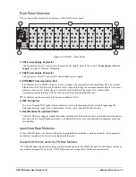
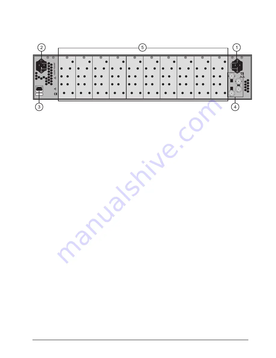
This section briefly summarizes the features of the OGX-FR rear panel.
Figure 3.3 OGX-FR — Rear Panel
1. PS1 Power Supply Connector
This connector is the AC Connector for the main power supply. Refer to the section “
” on page 19 for more information.
2. PS2 Power Supply Connector
This connector is the AC Connector for the redundant power supply.
3. ETHERNET Communication Port
The Ethernet port is an RJ45 connector is used to connect the optional Network Controller card to an external
Ethernet network. This Network Controller card is required to bridge the external Ethernet network to the local
communication bus for monitoring and control of cards installed in the frame. Only cards with the
Communication bus interface will be able to be monitored and controlled this way.
The Ethernet port does not provide Power-over-Ethernet (PoE).
4. REF Connectors
Two sets of looping BNC inputs are provided to accept two independent reference signals supporting the
following reference signal types: Analog black, Tri-level sync, and AES/DARS reference.
5. Rear Modules for openGear Cards
The OGX-FR frame supports module-dependent rear modules. Rear modules can be ordered with cards, and are
easy and quick to install. Blank plates must be installed if the slots are not populated with openGear cards and
rear modules.
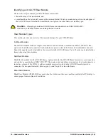
openGear Rear Modules
If your OGX-FR frame was ordered with cards requiring full rear modules or split rear modules, the appropriate
modules are installed at the factory or included with the cards.
Supports DFR-8321 and OG3-FR Rear Modules
The OGX-FR frame supports all existing rear modules designed for the DFR-8321 and OG3-FR frames. However,
rear modules designed for use in the OGX-FR frame are not compatible with other openGear frames.
PS1
100-240V~50-60Hz 600W
CAUTION: RISK OF SHOCK
DO NOT OPEN
REF 1
LOOP
REF 2
LOOP
PS2
ETHERNET
100-240V~50-60Hz 600W
CAUTION
RISK OF SHOCK DO NOT OPEN
OGX-FR


