


5-5
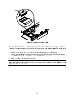
Warning: The heatsinks on the MBus modules may be hot. Use caution when removing or installing boot
PROMs and MBus modules and avoid contact with the heatsinks. Hold MBus modules only by the edges.
1. Locate the boot PROMs, carefully noting the position of each and its respective number, i.e., 1, 2, 3,
or 4 (of 4). Refer to Figure 5-3 for the correct number and position of each boot PROM.
2. Carefully replace each of the old boot PROMs with a new boot PROM of the same number, i.e., 1, 2,
3, or 4 (of 4). These are supplied with the new hyperSPARC module. Ensure that each new boot
PROM is firmly seated in its correct socket.
Caution:
Boot PROMs must be replaced in the correct numbered locations. Failure to do so can yield
unpredictable results.
Note: Be sure to save the original boot PROMs and module(s) in the new packaging after installation so that
they can be used later if needed.
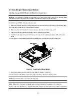
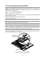
5.4 Removing the Module
Caution: Use ESD kit P/N 250-1088 (or equivalent) when installing integrated circuits, printed circuit boards,
and drives in a SPARCserver 600MP. ESD kit P/N 250-1088 contains the Sun approved ESD mat that has
0.25” of cushioning to protect underside components, prevent board flexing, and provide ESD protection.
Follow the instructions printed on the ESD mat and use the wrist grounding strap.
To remove an MBus module, first remove the system board from the card cage. Then refer to Section 5.2
“Removing the System Board from the Enclosure.”
1. Remove the slotted fillister head screw from each standoff of the module.
Keep these screws to use when installing a replacement hyperSPARC module.
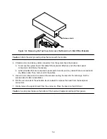
Figure 5-4. Removing the MBus Modules
Summary of Contents for hyperSPARC
Page 2: ...hyperSPARC Module Installation Guide TM...
Page 9: ...1 4...
Page 21: ...2 12...
Page 55: ...5 10...