OXYMITTER 4000OXYGEN TRANSMITTER
Instruction Bulletin IB-106-340
Revision 2.2
Oxymitter 4000
Part no.
____________
Serial no.
Order no.
26170020
STAY OFF THE STACK!
HART/AMS
Cal
Recommended
Autocal
Page 1: ...000 OXYGEN TRANSMITTER Instruction Bulletin IB 106 340 Revision 2 2 Oxymitter 4000 Part no ____________ Serial no ____________ Order no ____________ 26170020 STAY OFF THE STACK HART AM S Cal Recom m ended Autocal ...
Page 2: ...te disassembly recommendation from paragraph 2 1 b 2 Page 2 7 Changed horizontal to vertical in paragraph 2 1 b 5 Page 2 9 Added CE compliance NOTE Page 3 2 Added 0 to 40 O2 range to paragraphs 3 1 c 2 and 3 1 e 2 Page 3 4 Expanded paragraphs 3 2 3 2 a and 3 2 b to further describe logic I O Changed 1 Kohm to 330 ohm in paragraph 3 2 a Pages 5 1 through 5 20 Moved TROUBLESHOOTING from Section VI t...
Page 3: ...ION concerning uninsulated stacks and ambient temperatures Page 2 9 Added paragraph 2 2 c 3 concerning alarm contacts without autocalibration Page 2 10 Modified paragraph 2 3 Added paragraphs 2 3 a and b concerning autocalibration and alarms contacts Page 3 5 Added paragraph 3 3 concerning recommended configurations Subsequent paragraphs renumbered Page 5 1 Modified paragraph 5 2 to explain alarm ...
Page 4: ...rfreight Page 1 12 Updated the numbering of subsequent tables in Section I Page 2 9 Added references to step 2 to direct users to the information explaining the contacts and additional alarm contacts associated with the IMPS 4000 Page 2 10 Removed the IMPS 4000 information from paragraph 2 3 Page 5 11 Removed step 2 explaining that a 204 mV to 1 volt DC value indicated high combustibles Pages 8 1 ...
Page 5: ... s sole remedy ies for any failure of Rosemount to comply with the warranty provisions whether claims by the purchaser are based in contract or in tort including negligence Rosemount does not warrant equipment against normal deterioration due to environ ment Factors such as corrosive gases and solid particulates can be detrimental and can create the need for repair or replacement as part of normal...
Page 6: ...h the Description and Installation sections before installing your transmitter The description presents the basic principles of the transmitter along with its performance characteristics and components The remaining sections contain detailed procedures and information necessary to install and service the transmitter Before contacting Rosemount concerning any questions first consult this manual It ...
Page 7: ...only be made through a circuit breaker which will disconnect all circuits carrying conductors during a fault situation The circuit breaker may also include a mechanically operated isolating switch If not then another means of disconnecting the equipment from the supply must be provided and clearly marked as such Circuit breakers or switches must comply with a recognized standard such as IEC947 All...
Page 8: ... veilige werking van dit toestel te verzekeren moet de voeding door een stroomonderbreker gevoerd worden min 10A welke alle draden van de voeding moet onderbreken De stroomonderbreker mag een mechanische schakelaar bevatten Zoniet moet een andere mogelijkheid bestaan om de voedingsspanning van het toestel te halen en ook duidelijk zo zijn aangegeven Stroomonderbrekers of schakelaars moeten onderwo...
Page 9: ...kabes beskyttelse mod indirekte berøring gennem afbryder min 10A som vil afbryde alle kredsløb med elektriske ledere i fejlsitua tion Afbryderen skal indholde en mekanisk betjent kontakt Hvis ikke skal anden form for afbryder mellem forsyning og udstyr benyttes og mærkes som sådan Afbrydere eller kontakter skal overholde en kendt standard som IEC947 7 Hvor udstyr eller dæksler er mærket med dette ...
Page 10: ...a een meerpolige automatische zekering min 10A die alle spanningvoerende geleiders verbreekt indien een foutconditie optreedt Deze automatische zekering mag ook voorzien zijn van een mechanisch bediende schakelaar Bij het ontbreken van deze voorziening dient een andere als zodanig duidelijk aangegeven mogelijkheid aanwezig te zijn om de spanning van de apparatuur af te schakelen Zekeringen en scha...
Page 11: ...an varmistamiseksi täytyy jännitesyöttö varustaa turvakytkimellä min 10A joka kytkee irti kaikki jännitesyöttöjohtimet vikatilanteessa Suojaan täytyy myös sisältyä mekaaninen erotuskytkin Jos ei niin jännitesyöttö on pystyttävä katkaisemaan muilla keinoilla ja merkittävä siten että se tunnistetaan sellaiseksi Turvakytkimien tai kat kaisimien täytyy täyttää IEC947 standardin vaatimukset näkyvyydest...
Page 12: ...rs 6 Afin de garantir la sécurité du fonctionnement de cet appareil le raccordement à l alimentation électrique doit être réalisé exclusivement au travers d un disjoncteur minimum 10A isolant tous les conducteurs en cas d anomalie Ce disjoncteur doit également pouvoir être actionné manuellement de façon mécanique Dans le cas contraire un autre système doit être mis en place afin de pouvoir isoler ...
Page 13: ... den Geräten unterbrochen wird Ein mechanischer Schutzschalter kann in dieses System integriert werden Falls eine derartige Vorrichtung nicht vorhanden ist muß eine andere Möglichkeit zur Unterbrechung der Spannungszufuhr gewährleistet werden mit Hinweisen deutlich gekennzeichnet werden Ein solcher Mechanismus zur Spannungsunterbrechung muß mit den Normen und Richtlinien für die allgemeine Install...
Page 14: ...ntire un sicuro funzionamento dello strumento il collegamento alla rete di alimentazione principale dovrà essere eseguita tramite interruttore automatico min 10A in grado di disattivare tutti i conduttori di circuito in caso di guasto Tale interruttore dovrà inoltre prevedere un sezionatore manuale o altro dispositivo di interruzione dell alimentazione chiaramente identificabile Gli interruttori d...
Page 15: ...nningsforsyningen til alle elektriske kretser ved en feilsituasjon Strømbryteren kan også inneholde en mekanisk operert bryter for å isolere instrumentet fra spenningsforsyningen Dersom det ikke er en mekanisk operert bryter installert må det være en annen måte å isolere utstyret fra spenningsforsyningen og denne måten må være tydelig merket Kretsbrytere eller kontakter skal oppfylle kravene i en ...
Page 16: ...pamento a ligação ao cabo de alimentação eléctrica deve ser feita através de um disjuntor min 10A que desligará todos os condutores de circuitos durante uma avaria O disjuntor poderá também conter um interruptor de isolamento accionado manualmente Caso contrário deverá ser instalado qualquer outro meio para desligar o equipamento da energia eléctrica devendo ser assinalado convenientemente Os disj...
Page 17: ...la alimentacion electrica se realizara a traves de un interruptor magnetotermico min 10 A el cual desconectara la alimentacion electrica al equipo en todas sus fases durante un fallo Los interruptores estaran de acuerdo a la norma IEC 947 u otra de reconocido prestigio 7 Cuando las tapas o el equipo lleve impreso el simbolo de tension electrica peligrosa dicho alojamiento solamente se abrira una v...
Page 18: ...mmen endast göras genom en säkring min 10A som skall frånkoppla alla strömförande kretsar när något fel uppstår Säkringen kan även ha en mekanisk frånskiljare Om så inte är fallet måste ett annat förfarande för att frånskilja utrustningen från strömförsörjning tillhandahållas och klart framgå genom markering Säkring eller omkopplare måste överensstämma med en gällande standard såsom t ex IEC947 7 ...
Page 19: ...IB 106 340 xv ...
Page 20: ...ilicon Dioxide CHEMICAL NAME N A CHEMICAL FORMULA N A MANUFACTURER S NAME AND ADDRESS Watlow Columbia 573 474 9402 2101 Pennsylvania Drive 573 814 1300 ext 5170 Columbia MO 65202 HEALTH HAZARD SUMMARY WARNING Possible cancer hazard based on tests with laboratory animals May be irritating to skin eyes and respiratory tract May be harmful if inhaled Cristobalite crystalline silica formed at high tem...
Page 21: ...uminosilicate vitreous 99 1 fiber cc TWA CAS No 142844 00 06 10 fibers cc CL Zirconium Silicate 0 10 5 mg cubic meter TLV Black Surface Coating 0 1 5 mg cubic meter TLV Armorphous Silica Silicon Dioxide 0 10 20 mppcf 6 mg cubic meter PEL OSHA 1978 3 gm cubic meter Respirable dust 10 mg cubic meter Intended TLV ACGIH 1984 85 Composition is a trade secret SECTION IV FIRE AND EXPLOSION DATA FLASH POI...
Page 22: ...n to cristobalite a form of crystalline silica which can cause severe respiratory disease Pneumoconiosis The amount of cristobalite present will depend on the temperature and length of time in service See Section IX for permissible exposure levels SPECIAL TOXIC EFFECTS The existing toxicology and epidemiology data bases for RCF s are still preliminary Information will be updated as studies are com...
Page 23: ...3 developed masotheliomas The International Agency for Research on Cancer IARC reviewed the carcinogenicity data on man made vitreous fibers including ceramic fiber glasswool rockwool and slagwool in 1987 IARC classified ceramic fiber fibrous glasswool and mineral wool rockwool and slagwool as possible human carcinogens Group 2B EMERGENCY FIRST AID PROCEDURES EYE CONTACT Flush eyes immediately wit...
Page 24: ...or suitable equipment Pending the results of long term health effects studies engineering control of airborne fibers to the lowest levels attainable is advised VENTILATION Ventilation should be used whenever possible to control or reduce airborne concentrations of fiber and dust Carbon monoxide carbon dioxide oxides of nitrogen reactive hydrocarbons and a small amount of formaldehyde may accompany...
Page 25: ...n order to critically evaluate and classify the cancer causing potential Based on its review IARC classified crystalline silica as a group 2A carcinogen probable human carcinogen The OSHA permissible exposure limit PEL for cristobalite is 0 05 mg m3 respirable dust The ACGIH threshold limit value TLV for cristobalite is 0 05 mg m3 respirable dust ACGIH 1991 92 Use NIOSH or MSHA approved equipment ...
Page 26: ...he work area To aid the wetting process a surfactant can be used After RCF removal is completed dust suppressing cleaning methods such as wet sweeping or vacuuming should be used to clean the work area If dry vacuuming is used the vacuum must be equipped with HEPA filter Air blowing or dry sweeping should not be used Dust suppressing components can be used to clean up light dust Product packaging ...
Page 27: ...4000 with SPS 4000 2 13 III STARTUP 3 1 3 1 General 3 1 3 2 Logic I O 3 4 3 3 Recommended Configuration 3 5 3 4 Power Up 3 6 3 5 Start Up Oxymitter 4000 Calibration 3 6 3 6 IMPS 4000 Connections 3 6 IV OPERATION 4 1 4 1 General 4 1 V TROUBLESHOOTING 5 1 5 1 General 5 1 5 2 Alarm Indications 5 1 5 3 Alarm Contacts 5 1 5 4 Identifying and Correcting Alarm Indications 5 2 5 5 SPS 4000 Troubleshooting...
Page 28: ...cator PC Connections 7 2 7 4 Off line and On line Operations 7 3 7 5 Logic I O Configurations 7 3 7 6 Menu Tree For HART Communicator Oxymitter 4000 Applications 7 3 7 7 HART Communicator O2 CAL Method 7 7 7 8 Defining a Timed Calibration via HART 7 8 VIII REPLACEMENT PARTS 8 1 IX RETURNING EQUIPMENT TO THE FACTORY 9 1 X OPTIONAL ACCESSORIES 10 1 INDEX I 1 ...
Page 29: ...oop and Insulation Removal 2 8 2 9 Terminal Block 2 9 2 10 SPS 4000 Electrical Connections 2 11 2 11 Air Set Plant Air Connection 2 12 2 12 Oxymitter 4000 Gas Connections 2 12 3 1 Integral Electronics 3 1 3 2 Oxymitter 4000 Defaults 3 3 3 3 Startup and Normal Operation 3 5 3 4 Calibration Keys 3 6 4 1 Normal Operation 4 2 5 1 Fault 1 Open Thermocouple 5 3 5 2 Fault 2 Shorted Thermocouple 5 4 5 3 F...
Page 30: ...mbly 6 12 6 9 Cell Replacement Kit 6 13 6 10 Ceramic Diffusion Element Replacement 6 14 6 11 SPS 4000 Manifold Assembly 6 17 6 12 Power Supply Board and Interface Board Connections 6 18 6 13 Calibration Gas and Reference Air Components 6 21 7 1 Signal Line Connections 250 Ohms Lead Resistance 7 1 7 2 Signal Line Connections 250 Ohms Lead Resistance 7 2 7 3 Menu Tree for HART AMS on the Oxymitter 4...
Page 31: ... 12 1 5 Single Probe Autocalibration Sequencer Coding 1 12 3 1 Logic I O Configuration 3 4 5 1 Diagnostic Unit Alarm Fault Definitions 5 2 5 2 SPS 4000 Fault Finding 5 18 6 1 Diagnostic Unit Alarms 6 5 7 1 Logic I O Configuration 7 3 8 1 Replacement Parts for Probe 8 1 8 2 Replacement Parts for Electronics 8 5 8 3 Replacement Parts for SPS 4000 8 7 8 4 Replacement Parts for Calibration Components ...
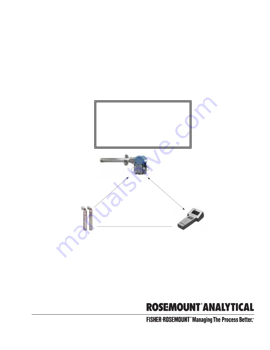
Page 32: ...probe Test Gas Sequencer Optional 3 Oxymitter 4000 with Integral Electronics 4 SPS 4000 Single Probe Autocalibration Sequencer Optional Shown with reference air option 5 Adapter Plate with Mounting Hardware and Gasket 6 HART Communicator Package Optional 7 Reference Air Set used if SPS 4000 without reference air option or IMPS 4000 not supplied Figure 1 1 Typical System Package ...
Page 33: ...ed with porous metal electrodes When operated at the proper temperature the millivolt output voltage of the cell is given by the following Nernst equation EMF KT log10 P1 P2 C Where 1 P2 is the partial pressure of the oxygen in the measured gas on one side of the cell 2 P1 is the partial pressure of the oxygen in the reference air on the opposite side of the cell 3 T is the absolute temperature 4 ...
Page 34: ...tems with one or two Oxymitter 4000 units per combustion process an optional SPS 4000 Single Probe Autocalibration Sequencer can be used with each Oxymitter 4000 to provide automatic calibration gas sequencing The SPS 4000 can be mounted directly to the Oxymitter 4000 or in a remote location if space is limited The sequencer performs autocalibrations based on the CALIBRATION RECOMMENDED signal fro...
Page 35: ...VII HART AMS for additional information 2 Personal Computer PC The use of a personal computer requires AMS software available from Fisher Rosemount 3 Selected Distributed Control Systems The use of distributed control systems requires input output I O hardware and AMS software which permit HART communications c Optional IMPS 4000 The Program mable Logic Controller PLC in the IMPS 4000 provides fau...
Page 36: ...event breathing of the calibration gas line and subsequent flue gas condensation and corrosion The check valve is in addition to the stop valve in the calibration gas kit or the solenoid valves in the IMPS 4000 or SPS 4000 NOTE The integral electronics is rated NEMA 4X IP66 and is capable of operation at temper atures up to 149 F 65 C Retain the packaging in which the Oxymit ter 4000 arrived from ...
Page 37: ...EFERENCE AIR OPTION CALIBRATION GAS 1 HIGH GAS CALIBRATION CALIBRATION CALIBRATION GAS 2 LOW GAS ADAPTER PLATE 4 20 mA SIGNAL RELAY OUTPUTS AND REMOTE CONTACT INPUT STACK DUCT GASES INSTRUMENT AIR SUPPLY LINE VOLTAGE IMPS 4000 OPTION IMPS 4000 REFERENCE AIR LOGIC I O CALIBRATION GAS ADAPTER PLATE STACK DUCT GASES CALIBRATION GAS 1 CALIBRATION GAS 2 INST AIR SUPPLY LINE VOLTAGE 4 TO 20 mA SIGNAL 26...
Page 38: ...an Oxymitter 4000 or at a remote loca tion if space is limited In addition the integrally mounted SPS 4000 can be configured for a hori zontally or vertically mounted Oxymitter 4000 Figure 2 2 The information in this instruction bulletin will cover the integrally mounted units only For information on remote mounted units re fer to the SPS 4000 Single Probe Autocalibration Sequencer Instruction Bul...
Page 39: ...peration The SPS 4000 works in conjunction with the Oxymitter 4000 s CALIBRATION RECOMMENDED feature to perform an auto calibration This feature automatically performs a gasless calibration check every hour on the Oxymitter 4000 If a calibration is recommended and its contact output signal is set for handshaking with the sequencer the Oxymitter 4000 sends a signal to the sequencer The se quencer a...
Page 40: ... N2 8 O2 Balance N2 Calibration Gas Flow 5 scfh 2 5 l m Reference Air 2 scfh 1 l m clean dry instrument quality air 20 95 O2 regulated to 5 psi 34 kPa Electronics NEMA 4X IP66 with fitting and pipe on reference exhaust port to clear dry atmosphere Electronic Noise Meets EN 50082 2 Generic Immunity Std Part II Includes EN 61000 4 2 for Electrostatic Discharge 4 KV contact 8 KV in air Includes IEC 8...
Page 41: ...v 1 Group B C D Electrical Feedthroughs 1 2 in NPT Input Power 90 to 250 VAC 50 60 Hz Power Consumption 5 VA maximum External Electrical Noise EN 50 082 2 includes 4 KV electrostatic discharge Handshake Signal to from Oxymitter 4000 self powered 5 V 5 mA maximum Cal Initiate Contact Input from Control Room 5 VDC self powered Relay Outputs to Control Room 5 to 30 VDC Form A SPST one In Cal one Cal ...
Page 42: ...1 6 9 ft 2 74 m Probe 7 9 ft 2 74 m Probe with Abrasive Shield 1 8 12 ft 3 66 m Probe 1 9 12 ft 3 66 m Probe with Abrasive Shield 1 Code Mounting Hardware Stack Side 0 No Mounting Hardware 0 must be chosen under Mounting Hardware Probe Side below 1 New Installation Square weld plate with studs 2 Mounting to Model 218 Mounting Plate with Model 218 Shield Removed 3 Mounting to Existing Model 218 Sup...
Page 43: ...upport brackets are recom mended for 9 ft 2 74 m and 12 ft 3 66 m probe installations particularly horizontal installations 2 Where possible specify SPS number otherwise provide details of the existing mounting plate as follows Plate with studs Bolt circle diameter number and arrangement of studs stud thread stud height above mounting plate Plate without studs Bolt circle diameter number and arran...
Page 44: ... V Heater 1 3D39695G10 IMPS w 220 V Heater 2 3D39695G11 IMPS w 220 V Heater 3 3D39695G12 IMPS w 220 V Heater 4 Table 1 4 Z Purge Option for Use with IMPS 4000 PART NUMBER DESCRIPTION 4513C24G03 Z Purge System for IMPS used with Oxymitter 4000 4513C24G03 Z Purge System for IMPS used with Oxymitter 4000 includes loss of purge switch WPS Table 1 5 Single Probe Autocalibration Sequencer Coding REF AIR...
Page 45: ...ences The ambient temperature of the integral electronics hous ing must not exceed 149 F 65 C 2 Check the flue or stack for holes and air leakage The presence of this condition will substantially affect the accuracy of the oxygen reading Therefore either make the necessary repairs or install the Oxymitter 4000 upstream of any leakage 3 Ensure the area is clear of internal and external obstructions...
Page 46: ...M HART SMART FAMILY REF GAS R H G T I N E W H C I T KE P E A I T C U EV L I M N I N L O A R P N I X E W G E S I V A T O S E H ER P 6 52 166 2 89 73 1 55 39 3 80 96 PROCESS FLOW MUST BE IN THIS DIRECTION WITH RESPECT TO DEFLECTOR 3534B48G01 DIA MAX 2 27 58 INSULATE IF EXPOSED TO AMBIENT WEATHER CONDITIONS ALL DIMENSIONS ARE IN INCHES WITH MILLIMETERS IN PARENTHESES NOTE 3535B18H02 3535B46H01 3535B4...
Page 47: ...NAL TO VIEW AND OPERATE OXYMITTER 4000 KEYPAD 12 00 304 80 NOMINAL TO VIEW AND OPERATE OXYMITTER 4000 KEYPAD 26170003 2 00 50 80 NOMINAL CLEARANCE TO REMOVE COVER HORIZONTAL MOUNTED SPS 4000 A VERTICAL MOUNTED SPS 4000 A 2 00 50 80 NOMINAL CLEARANCE TO REMOVE COVER 13 00 330 20 NOMINAL 2 00 50 80 1 2 IN CONDUIT FITTING FOR LINE VOLTAGE 1 2 NPT SIGNAL CONDUIT PORT CUSTOMER TO SUPPLY FITTING 0 94 23...
Page 48: ...CTION REF AIR CAL GAS ANSI ANSI ANSI 1 4 IN TUBE 6 mm TUBE 6 mm TUBE GAS CAL SNUBBER DUST SEAL ASSEMBLY 0 2 5 3 6 91 DIA NOMINAL 3 9 99 DIM A AND ARE NOT PRESSURE RATED 1 THESE FLAT FACED FLANGES ARE MANUFACTURED TO ANSI DIN AND JIS BOLT PATTERNS NOTES REMOVAL ENVELOPE DIM B 7 00 178 12 50 318 29340001 8 HOLES EQ SP ON BC 3D39003 TABLE 4 ABRASIVE SHIELD HOLE DIA FLANGE DIA 9 00 229 9 25 235 9 25 2...
Page 49: ...16 x 2 3 94 100 7 48 190 5 708 145 M 16 x 2 6 50 165 9 25 235 M 12 x 1 75 4 92 125 7 894 200 5 118 130 M 20 x 2 5 PART NUMBERS FOR ADAPTER PLATES INCLUDE ATTACHING HARDWARE PART NUMBERS FOR ADAPTER PLATES INCLUDE ATTACHING HARDWARE ADAPTER PLATE FOR 3 6 9 AND 12 FT ABRASIVE SHIELD INSTALLATIONS SEE FIGURE 2 3 CROSSHATCHED AREA IN 4 CORNERS MAY BE USED TO PROVIDE ADDITIONAL HOLES FOR FIELD BOLTING ...
Page 50: ... BY CUSTOMER MASONRY STACK WALL OUTSIDE WALL SURFACE JOINT MUST BE AIRTIGHT MTG HOLES SHOWN ROTATED 45 OUT OF TRUE POSITION o FIELD WELD PIPE TO ADAPTER PLATE BOLT ADAPTER PLATE TO OUTSIDE WALL SURFACE NOTE DIMENSIONS IN INCHES WITH MILLIMETERS IN PARENTHESES 2 50 63 5 MIN DIA HOLE IN WALL STACK OR DUCT METAL WALL WELD OR BOLT ADAPTER PLATE TO METAL WALL OF STACK OR DUCT JOINT MUST BE AIRTIGHT FIE...
Page 51: ...re 2 6 Oxymitter 4000 Bracing Installation 4 If using the optional ceramic diffusion element the vee deflector must be correctly oriented Before inserting the Oxymitter 4000 check the direction of gas flow in the duct Orient the vee deflector so the apex points upstream toward the flow Figure 2 7 This may be done by loosening the setscrews and rotating the vee deflector to the desired position Ret...
Page 52: ...des into the 15 forcing cone in the abrasive shield NOTE If process temperatures will exceed 392 F 200 C use anti seize compound on stud threads to ease future removal of Oxymitter 4000 7 Insert probe through the opening in the mounting flange and bolt the unit to the flange When probe lengths selected are 9 or 12 ft 2 74 or 3 66 m special brackets are supplied to provide additional support for th...
Page 53: ...ver lock 34 Remove terminal block cover 27 b Connect Line Voltage Connect the line or L1 wire to the L1 terminal and the neutral or L2 wire to the N terminal Figure 2 9 The Oxymitter 4000 automatically will configure itself for 90 250 VAC line voltage and 50 60 Hz The power supply requires no setup c Connect 4 20 mA Signal and Logic I O Calibration Handshake Leads Figure 2 9 1 4 20 mA Signal The 4...
Page 54: ...stments with no operator attention required The SPS 4000 provides solenoid valves and circuitry for calibrating a single Oxymitter 4000 unit The SPS 4000 autocalibration system utilizes the Oxymitter 4000 s bidirectional logic contact as a handshake signal Therefore this signal is not available for alarming purposes The following contacts are provided through the autocalibration system a One conta...
Page 55: ... out through the bottom of the manifold Connect the and CAL FAIL leads and the and IN CAL leads to terminals 7 8 9 and 10 respectively as shown in Figure 2 10 e Connect 4 20 mA Signal Wiring Route the 4 20 mA signal wiring into the manifold through the 1 2 in NPT signal conduit port Figure 2 2 and out through the bottom of the manifold Connect the and signal leads to terminals 3 and 4 respectively...
Page 56: ...unt Analytical Inc Orrville OH 44667 0901 85 264 VAC 48 62 Hz TM 800 433 6076 4 20 mA R 5 Amps TM HART SMART FAMILY Figure 2 11 Air Set Plant Air Connection 2 4 PNEUMATIC INSTALLATION FOR OXY MITTER 4000 WITHOUT SPS 4000 a Reference Air Package After the Oxymitter 4000 is installed connect the reference air set to the Oxymitter 4000 The reference air set should be installed in accordance with Figu...
Page 57: ... reference air flowmeter pressure regulator and necessary tubing and fittings is used connect the instru ment air to the 1 4 in fitting on the reference air pressure regulator Figure 2 2 The pressure regulator is factory set at 20 psi 138 kPa Read just by turning the knob on the top of the regula tor to obtain the desired pressure If the SPS 4000 does not have the reference air option connect the ...
Page 58: ... gasket 33 and screw 32 4 For an Oxymitter 4000 with an integrally mounted SPS 4000 remove screws 26 Figure 6 11 and terminal cover 27 Check that the power and signal terminations are properly connected to terminal strip 25 and secure according to instructions in Sec tion II INSTALLATION 5 Install terminal cover 27 and secure with screws 26 AC L1 AC N 4 20 500 VA SERIAL NO TAG NO OXYMITTER 4000 WA...
Page 59: ...probe s sensing cell which is in direct contact with the process gases is heated to approximately 1357 F 736 C and the external temperature of the probe body may exceed 842 F 450 C If operating conditions also con tain high oxygen levels and combustible gases the Oxymitter 4000 may self ignite If necessary the O2 range can be configured from 0 to 40 O2 To select values within this range set positi...
Page 60: ...RG TP4 TP5 TP6 ON INTERNAL 4 20 mA IS INTERNALLY POWERED DEFAULT EXTERNAL 4 20 mA REQUIRES AN EXTERNAL POWER SUPPLY HART 0 TO 10 O2 4 mA NOT USED NOT USED 0 TO 25 O2 LOCAL 20 mA DEFAULT POSITION EX FACTORY 4 mA 20 mA 0 TO 25 O 2 0 TO 10 O 2 LOCAL HART O RANGE SET BY HART AMS FROM 0 TO 40 O O RANGE SET BY POS 2 O RANGE WHEN ALARM EXISTS OR ON POWER UP CURRENT OUTPUT GOES TO THIS VALUE 2 2 2 2 1 2 3...
Page 61: ...For an Oxymitter 4000 with an IMPS 4000 or an SPS 4000 the factory sets the default to mode 8 In this mode the logic I O will be used to commu nicate between the Oxymitter 4000 and se quencer and to signal the sequencer when a CALIBRATION RECOMMENDATION indica tion occurs Table 3 1 Logic I O Configuration Mode Configuration 0 The unit is not configured for any alarm condition 1 The unit is configu...
Page 62: ... days or weeks since previous calibration When utilizing the SPS 4000 or the IMPS 4000 consider wiring some or all associated alarm contacts 1 CALIBRATION INITIATE Contact from the control room to an SPS 4000 or IMPS 4000 one per probe provides the ability to manually initiate a calibration at any time from the control room Note that calibrations can also be initiated from a HART handheld communic...
Page 63: ...e 3 3 c Error If there is an error condition at startup one of the diagnostics LEDs will be blinking Re fer to Section V TROUBLESHOOTING to de termine the cause of the error Clear the error cycle power and the operating display should return d Keypad The five membrane keys on the membrane keypad are only used during calibra tion to adjust the high and low gas and to initiate the calibration sequen...
Page 64: ... b TP3 and TP4 monitor the heater thermocouple c TP5 and TP6 monitor the process gas or the calibration gas parameter 4 CAL LED The CAL LED is on steady or flashing during calibration Further informa tion is available in Section VI MAINTENANCE AND SERVICE 5 Keys a INC and DEC The INC and DEC keys are used to set the values of the calibration gases Attach a multimeter across TP5 and TP6 The calibra...
Page 65: ... 3 4 1 2 3 4 DIAGNOSTIC ALARMS TEST POINTS HEATER T C HEATER O2 CELL CALIBRATION CALIBRATION RECOMMENDED O2 CELL mV O2 CELL mv HEATER T C HEATER T C INC INC DEC DEC HIGH GAS LOW GAS CAL TEST GAS PROCESS O2 SW2 TP1 J1 TP2 TP3 RED YEL GRN ORG TP4 TP5 TP6 ON CAL LED 22220055 Figure 4 1 Normal Operation ...
Page 66: ...the Oxymitter 4000 will be indicated by one of the four LEDs referred to as diagnostic or unit alarms on the operator s keypad An LED will flash a code that will correspond to an error message Only one LED will blink at a time An alarm code guide is provided inside the screw cover for the electronics All alarm indications will be available via the HART Model 275 handheld communicator and Rosemount...
Page 67: ...line and a fault number that corresponds to the troubleshooting instructions provided in this section Table 5 1 Diagnostic Unit Alarm Fault Definitions LED FLASHES STATUS 4 20 mA LINE FAULT SELF CLEARING HEATER T C 1 OPEN Dependent on position 3 of SW2 1 NO 2 SHORTED Dependent on position 3 of SW2 2 NO 3 REVERSED Dependent on position 3 of SW2 3 NO HEATER 1 OPEN Dependent on position 3 of SW2 4 NO...
Page 68: ...rmocouple a Fault 1 Open Thermocouple The HEATER T C LED flashes once pauses for three seconds and repeats Figure 5 1 1 Check connector J1 Ensure the connector is properly seated 2 Using a multimeter measure TP3 to TP4 If the reading is 1 2 VDC 0 1 VDC the thermocouple is open 3 Remove power Disconnect J1 Measure continuity across the red and yellow thermo couple leads 4 The measurement should rea...
Page 69: ...220034 Figure 5 2 Fault 2 Shorted Thermocouple b Fault 2 Shorted Thermocouple The HEATER T C LED flashes twice pauses for three seconds and repeats Figure 5 2 1 Using a multimeter measure across TP3 and TP4 2 If the reading is 0 0 5 mV then a shorted thermocouple is likely 3 Remove power and disconnect J1 4 Measure from TP3 to TP4 The reading should be approximately 20 Kohms 5 If so the short is n...
Page 70: ...N 22220035 Figure 5 3 Fault 3 Reversed Thermocouple c Fault 3 Reversed Thermocouple The HEATER T C LED flashes three times pauses for three seconds and repeats Figure 5 3 1 Using a multimeter measure TP3 to TP4 2 If the reading is negative the thermocouple wiring is reversed 3 Check red and yellow wires in the J1 connector for the proper placement 4 If the wiring is correct the fault is in the PC ...
Page 71: ... GRN ORG TP4 TP5 TP6 ON 22220036 Figure 5 4 Fault 4 Open Heater d Fault 4 Open Heater The HEATER LED flashes once pauses for three seconds and re peats Figure 5 4 1 Remove power Remove the electronic assembly per paragraph 6 5b Electronic As sembly Replacement 2 Using a multimeter measure across the heater connector J8 3 The measurement should be approximately 72 ohms If the heater is open see par...
Page 72: ...5 High High Heater Temp e Fault 5 High High Heater Temp The HEATER LED flashes twice pauses for three seconds and repeats Figure 5 5 1 The high high heater temp alarm will activate when the thermocouple produces a voltage of 37 1 mV 1652 F 900 C 2 The triac and the temperature control may be at fault 3 Remove power Allow Oxymitter 4000 to cool for five minutes Restore power 4 If the condition repe...
Page 73: ...or three seconds and repeats Figure 5 6 1 If the case temperature exceeds 185 F 85 C the temperature control will shut off and the 4 20 mA signal output will go to the default value 2 This signifies that the environment where the Oxymitter 4000 is installed exceeds the ambient temperature requirements or that heat due to convection is causing case tem perature to rise above the limit 3 Placing a s...
Page 74: ...igure 5 7 1 The low heater temperature alarm is active when the thermocouple reading has dropped below 28 6 mV 2 If the thermocouple reading continues to ramp downward for one minute and does not return to the temperature set point of ap proximately 29 3 mV then an Open Heater fault will be displayed 3 Power down the electronics Remove the electronic assembly per paragraph 6 5b Electronic Assembly...
Page 75: ...t 8 High Heater Temp The HEATER LED flashes five times pauses for three seconds and repeats Figure 5 8 1 If the thermocouple produces a voltage in excess of approximately 30 7 mV the high heater temp alarm activates 2 The 4 20 mA signal returns to the default value 4 or 20 mA 3 This alarm is self clearing When temperature control is restored and the thermocouple voltage returns to the normal range...
Page 76: ...e pauses for three seconds and repeats Figure 5 9 1 Using a multimeter measure across TP1 to TP2 2 If you measure 1 2 VDC the cell wires either orange or green have become de tached from the input 3 One possible cause is connector J1 The orange or green wire has come loose from the crimped connection 4 The platinum pad could also be at fault The pad could have broken free from the back of the cell...
Page 77: ...TEST GAS PROCESS O2 SW2 TP1 J1 TP2 TP3 RED YEL GRN ORG TP4 TP5 TP6 ON 22220042 Figure 5 10 Fault 10 Bad Cell j Fault 10 Bad Cell The O2 CELL flashes three times pauses for three seconds and repeats Figure 5 10 1 The bad cell alarm activates when the cell exceeds the maximum resistance value 2 The cell should be replaced See paragraph 6 8 Cell Replacement for cell replacement instructions ...
Page 78: ... k Fault 11 EEPROM Corrupt The O2 CELL LED flashes four times pauses for three seconds and repeats Figure 5 11 1 This alarm can occur if the EEPROM is changed for a later version At power up the EEPROM is not updated 2 To correct this problem power down and then restore power The alarm should clear 3 If the alarm occurs while the unit is running there is a hardware problem on the micro processor b...
Page 79: ...nds and repeats Figure 5 12 1 During a calibration the electronics calculates a slope value If the value of the slope is less than 35 mV deg or more than 52 mV deg the slope alarm will be active until the end of the purge cycle 2 See paragraph 6 2 Calibration Verify the calibration by carefully repeating it Ensure the calibration gases match the calibration gas parameters If you attach a multimete...
Page 80: ...stant m Fault 13 Invalid Constant The CALIBRA TION LED flashes twice pauses for three sec onds and repeats Figure 5 13 1 After a calibration has been performed the electronics calculates a cell constant value 2 If the cell constant value is outside of the range 4 mV to 10 mV the alarm will acti vate See paragraph 6 2 Calibration and verify the last calibration was performed correctly 3 Power down ...
Page 81: ...P6 ON 22220044 Figure 5 14 Fault 14 Last Calibration Failed n Fault 14 Last Calibration Failed The CALIBRATION LED flashes three times pauses for three seconds and repeats Figure 5 14 1 The last calibration failed alarm activates when the slope and constant values calcu lated are out of range and the unit reverts to using the previous calibration values 2 The cell should be replaced See paragraph ...
Page 82: ... menu the failure is due to either a bad Oxymitter 4000 cell or a calibration gas flow problem a Verify your calibration setup per paragraph 6 2 in Section VI MAINTENANCE AND SERVICE Also verify your calibration gas setup b Perform another calibration and monitor the process If the calibration fails before both calibration gases finish sequencing a gas flow problem exists Refer to Table 5 2 or Fig...
Page 83: ...w calibration gas to flow Calibration gas line between manifold and calibration gas flowmeter Clogged calibration gas line Replace clogged calibration gas line Fuse on power supply board Blown fuse Replace fuse per paragraph 6 10a Interface board operation Interface board not sending signals Replace interface board per paragraph 6 10b Check valve Clogged check valve Replace check valve per paragra...
Page 84: ... AND MANIFOLD REPLACED CLOGGED CAL GAS LINE BETWEEN MANIFOLD AND CAL GAS FLOWMETER 27610001 PROPERLY CONNECT WIRING OR SECURE LOOSE WIRING CON NECTIONS REPLACE DAMAGED WIRING REPLACE FUSE PER PARAGRAPH 6 10 a SYMPTOM NO TEST GAS FLOW NO NO NO NO YES YES YES YES YES NO CONTINUED ON SHEET 2 OF 2 IS WIRING PROPERLY CONNECTED AND SECURE IS FUSE BLOWN IS LOGIC I O SET FOR MODE 8 IS THERE FLOW DOES CAL ...
Page 85: ...ONNECT SOLENOID FROM POWER SUPPLY BOARD AND USE METER TO MEASURE ACROSS TWO OUTER PINS OF BOARD CONNECTOR SEE NOTE 4 CHECK BOTH SOLENOIDS REPLACE CHECK VALVE PER PARAGRAPH 6 10e SEE NOTE 3 REPLACE CLOGGED CAL GAS LINE BETWEEN CAL GAS FLOWMETER AND CHECK VALVE DISCONNECT CAL GAS LINE AT TOP FITTING OF CAL GAS FLOWMETER REPLACE FAULTY CAL GAS FLOWMETER PER PARAGRAPH 6 10h YES YES CONTINUED FROM SHEE...
Page 86: ...00 to return to the normal process reading after the last calibration gas is removed and the calibration gas line is blocked off A plugged element also can be indicated by a slightly lower reading on the flowmeter Change the diffusion element when the calibration gas flowmeter reads slightly lower during calibra tion or when the response time to the process flue gases becomes very slow Each time t...
Page 87: ...trut Assembly 2 Diffusion Assembly Snubber 3 Retainer Screw 4 Cell and Flange Assembly 5 Corrugated Seal 6 Probe Tube Assembly 7 Screw 8 Tube Connector 9 Gas Port 10 O ring 11 Right Housing Cover 12 Electronic Assembly 13 Screw 14 Membrane Keypad 15 Snap Connector 16 Captive Screw 17 Microprocessor Board 18 Fuse Cap 19 Fuse 20 Power Supply Board 21 Electronic Housing 22 Screw 23 Lock Washer 24 Cab...
Page 88: ...mmunicate Depending on your system setup a semi automatic calibration can be initiated by the following methods a Oxymitter 4000 Press the CAL key on the Oxymitter 4000 keypad b IMPS 4000 Use the IMPS 4000 keypad to change the InitCalX parame ter of the CHANGE PRESETS display mode from 0000 to 0001 Refer to the IMPS 4000 Intelligent Multiprobe Test Gas Sequencer Instruction Bulletin for more infor...
Page 89: ... 1 d If performing a manual calibration with CALIBRATION RECOMMENDED LED on and the CAL LED on start at step 2 1 Push the CAL key The CALI BRATION RECOMMENDED LED will come on and the CAL LED will be on solid If a mul timeter is attached across TP5 and TP6 the reading will display the percentage of oxygen seen by the cell 2 Push the CAL key The CALIBRA TION RECOMMENDED LED will turn off and the CA...
Page 90: ...value and begins to read the process O2 If the calibration was valid the DIAGNOSTIC ALARMS LEDs will indicate normal operation If the new calibration values slope or constant is not within the parameters the DIAGNOSTIC ALARMS LED will indicate an alarm See Section V TROUBLESHOOTING for alarm codes If the calibration was invalid the Oxymitter 4000 will return to normal operation as it was before a ...
Page 91: ... on the AC terminal cover and slide the cover back to access the neutral and line terminals Loosen the AC line and neutral terminal screws and remove the leads Loosen the ground lug screws and remove the leads Slide the line power leads out of the AC line voltage port f Loosen the logic I O and the 4 20 mA signal terminal screws Remove the leads from the terminals and slide the wires out of the si...
Page 92: ...ugh the SPS 4000 disconnect the instrument air directly at the Oxymitter 4000 d Remove the screws securing the ter minal cover to the SPS 4000 manifold Remove the terminal cover to expose the terminal strip e Tag all customer wired leads that are connected to the terminal strip before removing f On the terminal strip loosen the screws securing the customer wired LINE IN and NEUTRAL leads to termin...
Page 93: ...nd replace a specific electronic component of the Oxymit ter 4000 a Entire Electronics Replacement with Housing NOTE Only perform this procedure on Oxymitter 4000 units without integrally mounted SPS 4000 units If it is necessary to replace the entire electronics on an Oxymitter 4000 SPS 4000 assembly contact Rosemount for further instructions 1 Follow the instructions in paragraph 6 4a1 to remove...
Page 94: ... 12 Replace the housing cover and ensure it is tight 13 Follow the instructions in paragraph 6 4a2 to install the Oxymitter 4000 into the stack or duct If installing an Oxymitter 4000 SPS 4000 assembly follow the instructions in paragraph 6 4b2 b Electronic Assembly Replacement Figure 6 5 1 Remove the right housing cover uncovering the electronic assembly 2 Depress and remove the J1 cell and T C c...
Page 95: ...mounting screws on the micro processor board top board 3 The J8 connector heater leads can be accessed by moving the J1 connector leads out of the slot on the microprocessor board and sliding the electronic assembly partially out of the housing Figure 6 6 4 Squeeze the J8 connector on the sides and carefully remove The electronic assembly can now be completely removed from the housing 3 D 3 9 6 1 ...
Page 96: ...ymitter 4000 with an integrally mounted SPS 4000 follow the instructions in paragraph 6 4b1 b Separate the probe and the electronics housing per paragraph 6 5a steps 2 through 6 c Reinstall electronics on the new probe per paragraph 6 5a steps 7 through 13 6 7 HEATER STRUT REPLACEMENT This paragraph covers heater strut replacement Do not attempt to replace the heater strut until all other pos sibi...
Page 97: ...obe tube Slide the strut into the probe tube It will turn to align the hole on the back plate of the strut with the calibration gas line When the hole and the calibration gas line are aligned correctly the strut will slide in the rest of the way g Push down on the back plate of the strut to make sure you have spring tension and then tighten the three screws on the back plate h Replace the CAL and ...
Page 98: ...d hex wrenches needed for this procedure are part of an available special tools kit Table 8 1 Use heat resistant gloves and clothing when removing the probe Do not attempt to work on these components until they have cooled to room temperature Probe components can be as hot as 800 F 427 C This can cause severe burns Disconnect and lock out power before working on any electrical components There is ...
Page 99: ...reads on the retainer and hub h Rub a small amount of anti seize compound on both sides of the new corrugated seal i Assemble the cell and flange assembly corrugated seal and probe tube Make sure the calibration tube lines up with the calibration gas passage in each component Apply a small amount of anti seize compound to the screw threads and use the screws to secure assembly Torque to 35 in lbs ...
Page 100: ...ment by tapping lightly around hub with hammer Clean grooves with pointed tool if necessary 7 Replace ceramic diffusion element using the ceramic diffusion element replacement kit in Table 8 1 This consists of a diffusion ele ment cement setscrews anti seize com pound and instructions 8 Test fit replacement ceramic diffusion element to be sure seat is clean Do not get cement on ceramic diffusion e...
Page 101: ...ing manifold cover lock 6 and remove the lock 3 Remove manifold cover 14 4 Remove two screws 11 attaching spacers 9 to manifold 5 5 Being careful not to disconnect the board wiring carefully lift power supply board 18 and interface board 19 from manifold 5 and set aside Do not lose O rings 8 from the bottom of spacers 9 6 Tag all leads on the board to be replaced to simplify installation 7 See Fig...
Page 102: ...asket 5 Manifold 6 Manifold Cover Lock 7 Screw 8 O Ring 9 Spacer 10 Screw 11 Screw 12 Pressure Switch 13 Calibration Gas 2 Solenoid 14 Manifold Cover 15 Cover O Ring 16 Fuseholder 17 Fuse 18 Power Supply Board 19 Interface Board 20 Calibration Gas 1 Solenoid 21 Washer 22 Stop Nut 23 Ground Nut 24 Terminal Base 25 Terminal Strip 26 Screw 27 Terminal Cover 28 Terminal Cover Gasket 29 Screw 30 Screw ...
Page 103: ...TER 4000 L1 LOGIC I O HANDSHAKE TO OXYMITTER 4000 WHITE RED BLUE ORANGE GREEN VIOLET GRAY Figure 6 12 Power Supply Board and Interface Board Connections c Solenoid Replacement The SPS 4000 manifold has a calibration gas 1 high calibration gas solenoid 20 Figure 6 11 and a calibration gas 2 low calibration gas solenoid 13 1 Turn off power to the system 2 Shut off the calibration gases at the cylind...
Page 104: ...eplacement Use the following procedure to replace pressure switch 12 Figure 6 11 1 Turn off power to the system 2 Shut off the calibration gases at the cylinders 3 Remove screw 7 securing manifold cover lock 6 and remove the lock 4 Remove manifold cover 14 5 Remove two screws 11 attaching spacers 9 to manifold 5 6 Being careful not to disconnect the board wiring carefully lift the board and spacer...
Page 105: ...re 6 13 or calibration gas flowmeter 17 1 Turn off power to the system 2 Shut off the calibration gases at the cylinders 3 Loosen but do not remove four screws 13 securing flowmeter bracket 25 to the manifold 4 Flex the bottom of flowmeter bracket 25 downward and away to disengage and remove from the manifold 5 For reference air flowmeter 16 remove pressure regulator 8 by disconnecting tubing 11 f...
Page 106: ...ght Fitting 4 Elbow Fitting 5 Bracket 6 Screw 7 Conduit Fitting 8 Reference Air Pressure Regulator Optional 9 Straight Fitting Optional 10 Elbow Fitting Optional 11 Tubing Optional 12 Elbow Fitting Optional 13 Screw 14 Elbow Street Fitting Optional 15 Elbow Fitting 16 Reference Air Flowmeter Optional 17 Calibration Gas Flowmeter 18 Tubing 19 Check Valve 20 Flare Fitting 21 Elbow Fitting 22 Elbow S...
Page 107: ... energy is added to the loop The HART Communicator may be interfaced with a personal computer PC providing special software has been installed To connect the HART Communicator to a PC an interface adapter is required Refer to the proper HART Communicator documentation in regard to the PC interface option 7 2 HART COMMUNICATOR SIGNAL LINE CONNECTIONS The HART Communicator can connect to the Oxymitt...
Page 108: ...n explosive atmosphere 1 At a convenient point break the analog output 4 20 mA signal line and install the optional 250 ohm load resistor 2 Plug the load resistor into the loop connectors located on the rear panel of the HART Communicator 7 3 HART COMMUNICATOR PC CONNEC TIONS There is an option to interface the HART Communicator with a personal computer Load the designated AMS software into the PC...
Page 109: ...RT AMS The factory default condition is Mode 5 A list of possible configurations appear in Table 7 1 The Unit Alarm configuration available for Modes 1 3 5 and 7 refers to the diagnostic alarm faults in Table 5 1 7 6 MENU TREE FOR HART COMMUNICATOR OXYMITTER 4000 APPLICATIONS This section consists of a menu tree for the HART Communicator This menu is specific to Oxymitter 4000 applications Table 7...
Page 110: ... Error Const Last Cal Failed Cell mV Cell TC mV CJ mV VIEW FLD DEV mV STATUS AO Fixed Max Case Temp AO Saturated Operate Model Status Group 3 Status Group 2 Status Group 1 LOOP TEST Loop test method O2 Cal Optrak TG CalState PERFORM O2 CAL O2 CALIBRATE CalState TimeRemain Present O2 O2 CAL STATUS Cal slope Cal const Cell Imp LAST CALCONSTANTS Reset CalConstants method RESET CALCONSTANTS D A trim m...
Page 111: ...PurgeTime Cal Mode Cal Intrvl h Next CalTime h LoAlarmSP SENSORS LIMITS DISPLAYED SIGNAL CONDITION OUTPUT CONDITION O2 O2 CALIBRATION O2 ALARMS CONTINUED FROM SHEET 1 BASIC SETUP DETAILED SETUP PV AO ____ mA PV AO Alrm typ LOOP TEST D A TRIM Poll addr Num req preams Logic I O Pin State Logic I O Pin Mode Loop test method D A trim method No Alarm Unit Alarm Low O2 Alarm Low O2 Unit Alarm Cal Rec Ca...
Page 112: ...sr s n Fld dev rev Hardware rev Software rev Universal rev Optrak TG Tgtime PurgeTime LowTG HighTG Cal slope Cal const CellImp Imp Delta Slope Constant URV LRV LoAlarmSP I O Pin Mode Poll addr Num req preams DEVICE INFORMATION CAL INFO DEVICE CONFIG OUTPUTS CONFIG REVIEW 26170030 Figure 7 3 Menu Tree for HART AMS on the Oxymitter 4000 Sheet 3 of 3 ...
Page 113: ...creen and select menu item 2 O2 CAL STATUS to view menu item 1 CALSTATE menu item 2 TIMEREMAIN and menu item 3 PRESENT O2 as the calibration status updates f When CALSTATE displays APPLY GAS 2 re turn to the O2 CAL procedure g When the Loop should be removed from auto matic control warning appears press OK h At the APPLY GAS 2 status prompt select menu item 2 NEXT CAL STEP When the status dis play...
Page 114: ...arrow key or use the number keypad to select the menu item number To return to a preceding menu press the left arrow key a From the DEVICE SETUP screen select DETAILED SETUP b From the DETAILED SETUP screen select O2 CALIBRATION c From the O2 CALIBRATION screen select menu item 6 CAL MODE Set the CAL MODE to AUTO d Return to the O2 CALIBRATION screen and se lect menu item 7 CAL INTRVL e At the pro...
Page 115: ...tor and Ceramic Diffuser 6 1 1 thru 6 8 9 28 thru 31 3D39648G23 3D39649G23 3 JIS Probe with Flame Arrestor and Ceramic Diffuser 6 1 1 thru 6 8 9 28 thru 31 3D39648G24 3D39649G24 6 JIS Probe with Flame Arrestor and Ceramic Diffuser 6 1 1 thru 6 8 9 28 thru 31 3D39648G25 3D39649G25 9 JIS Probe with Flame Arrestor and Ceramic Diffuser 6 1 1 thru 6 8 9 28 thru 31 3D39648G26 3D39649G26 12 JIS Probe wit...
Page 116: ... Assy 6 1 1 3D39645G05 12 Heater Strut Assy 8 1 4847B61G02 ANSI 18 Cell Replacement Kit 8 1 4847B61G03 ANSI 3 Cell Replacement Kit 8 1 4847B61G04 ANSI 6 Cell Replacement Kit 8 1 4847B61G05 ANSI 9 Cell Replacement Kit 8 1 4847B61G06 ANSI 12 Cell Replacement Kit 8 1 4847B61G08 JIS 18 Cell Replacement Kit 8 1 4847B61G09 JIS 3 Cell Replacement Kit 8 1 4847B61G10 JIS 6 Cell Replacement Kit 8 1 4847B61G...
Page 117: ...KIT SOCKET HEAD CAP SCREWS CORRUGATED SEAL ANSI GASKET WIRE AND PAD ASSEMBLY ANTI SEIZE COMPOUND 22 GA WIRE SET SCREWS TEFLON TUBING CLOSED END CONNECTOR CELL AND FLANGE ASSEMBLY CALIBRATION GAS PASSAGE 22220068 Figure 8 1 Cell Replacement Kit ...
Page 118: ...Seal 2 1 4843B38G02 Snubber Diffuser with Dust Seal 2 1 3534B18G01 Ceramic Diffuser Hub Assy 2 1 3534B48G01 Vee Deflector Assy 4845B27G01 Stainless Steel Diffusion Assy 5 microns 4845B27G02 Stainless Steel Diffusion Assy 40 microns 4845B27G03 Stainless Steel Diffusion Assy 100 microns 4845B27G04 Stainless Steel Diffusion Assy with dust seal hub 5 microns 4845B27G05 Stainless Steel Diffusion Assy w...
Page 119: ...d Cover 6 1 12 3D39777G05 Electronic Assembly and keypad Spanish 6 1 25 08732 0002 0001 Termination Block Standard 6 1 11 5R10145G01 Cover 4850B10G05 Electronics Italian Standard 6 1 21 27 4849B95G01 Housing and Cover 6 1 12 3D39777G06 Electronic Assembly and keypad Italian 6 1 25 08732 0002 0001 Termination Block Standard 6 1 11 5R10145G01 Cover 4850B10G06 Electronics English Transient Protected ...
Page 120: ...s Italian Transient Protected 6 1 21 4849B95G01 Housing 6 1 12 3D39777G06 Electronic Assembly and keypad Italian 6 1 25 08732 0002 0002 Termination Block Transient Protected 6 1 11 5R10145G01 Cover 6 1 12 3D39777G01 Electronic Assembly 6 1 14 4849B72H01 Membrane Keypad English 6 1 14 4849B72H02 Membrane Keypad German 6 1 14 4849B72H03 Membrane Keypad French 6 1 14 4849B72H04 Membrane Keypad Spanis...
Page 121: ...3 Fuse 5A 250V 5 20 mm Slow Blow 6 11 19 4850B56G01 Interface Board 6 11 18 4850B54G01 Power Supply Board 6 11 12 7305A67H01 Pressure Switch 6 11 13 and 20 1A97905H01 Solenoid 6 11 8 120039 0077 O ring 6 11 28 4850B75H01 Terminal Cover Gasket 6 11 25 1A99147H01 Terminal Strip Table 8 4 Replacement Parts for Calibration Components FIGURE and INDEX No PART NUMBER DESCRIPTION 1A99119G01 Calibration G...
Page 122: ...te from which equipment was removed 4 Whether warranty or nonwarranty service is requested 5 Complete shipping instructions for return of equipment 6 Reference the return authorization number d Enclose a cover letter and purchase order and ship the defective equipment according to instructions provided in Rosemount Return Authorization prepaid to American Rosemount Analytical Inc RMR Department 12...
Page 123: ...ET MANAGEMENT SOLUTIONS AMS Asset Management Solutions AMS software works in conjunction with the HART Communication Protocol and offers the capability to communicate with all HART plant devices from a single computer terminal For more information call Rosemount Analytical at 1 800 433 6076 C H A N G I N G THE WAY YOU SEE Y O U R P L A N T FISHER ROSEMOUNT ASSET MANAGEMENT SOLUTIONS 26170010 BY PA...
Page 124: ...r more information call Rosemount Analytical at 1 800 433 6076 26170006 SPS 4000 SINGLE PROBE AUTOCALIBRATION SEQUENCER Rosemount Analytical specifically designed the SPS 4000 Single Probe Autocalibration Sequencer to provide the capability to perform automatic or on demand Oxymitter 4000 calibrations The system can be installed either as an integral component to an Oxymitter 4000 or at a remote l...
Page 125: ...been carefully designed to provide a more convenient and fully portable means of testing calibrating and servicing Rosemount Analytical s oxygen analyzers These lightweight disposable gas cylinders eliminate the need to rent gas bottles For more information call Rosemount Analytical at 1 800 433 6076 26170021 ...
Page 126: ... Control System 1 3 Drip Loop 2 7 2 8 E EEPROM 5 13 Electronic Noise 1 8 Electronics 1 0 1 1 1 2 1 3 1 4 1 8 6 8 6 9 6 10 6 11 8 5 8 6 Electronics Temperature 1 8 Electrostatic Discharge 5 1 Equipment Return 9 1 F Fuse 6 10 G Grounding 5 1 H HART 1 0 1 1 1 2 1 3 3 2 3 3 5 17 6 3 7 1 7 3 7 4 7 5 7 6 7 7 10 1 HART Communicator 1 3 7 1 7 2 7 3 10 1 HART Menu Tree 7 4 7 5 7 6 Heater 5 2 5 6 5 7 5 8 5 ...
Page 127: ... Electrical 2 10 Installation Pneumatic 2 13 Interface Board 5 17 5 18 5 20 6 16 6 17 6 18 Line Voltage 1 5 2 10 2 11 6 7 6 18 Manifold 1 6 Mounting 1 6 Noise External Electrical 1 9 S SPS 4000 Cont d Piping Distance 1 9 Power 1 9 Power Supply Board 5 17 5 19 6 16 6 17 6 18 Pressure Regulator 1 7 6 19 Pressure Switch 1 6 5 18 5 20 6 17 6 19 Reference Air Flowmeter 1 7 2 3 6 20 6 21 Relay Outputs 1...