background image


10 


CRYSTALVIEW PLUS USB INSTALLATION AND OPERATIONS MANUAL


Serial port 

The serial port is a DB9F on the local unit and DB9M on the remote unit.  
The serial port on the remote unit is the same as the DB9M serial connector 
on your computer. Serial devices such as Touchscreens can connect 
directly to the serial port on the remote unit 

Audio ports 

A set of powered computer speakers can connect directly to the CrystalView 
Plus USB remote unit’s line level audio out connector.  A powered or non-
powered microphone can connect to the Line level audio in (MIC) connector.  
 
If you are using a non-powered microphone on the Remote Unit, install the 
“MIC” jumper, if needed, to provide additional amplification. 


Applying power 

(All models) 

Plug in the power adapter to a 100/240-volt source and to the power 
connector on the Remote Unit.  Only use the power adapter provided 
with the CrystalView Plus USB.  Boot up the connected CPU and wait for 
it to completely boot-up.  The Local Units power is supplied from the 
CPUs USB port.  If additional power is required at the local unit due to 
extended cable lengths or only passing video through the CrystalView 
Plus USB, connect the op5V DC power adapter to the local units 
+5V DC power jack. 
 
With power applied, you should see the primary and secondary video on 
the remote unit’s monitors.  Verify that the keyboard and mouse 
connected to the remote unit function properly.  The video can be fine 
tuned to correct for patch panels and cable differences with simple 
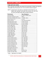
keyboard commands.  Table 1 shows the keyboard commands and key 
sequences used to initiate the command.   
 

DO NOT

 INSTALL THE “MIC” JUMPER IF USING A 

POWERED MICROPHONE. 
 

Summary of Contents for VideoSplitter CAT5

Page 1: ...CrystalView Plus USB ENHANCED CAT5 KVM EXTENDER 10707 Stancliff Road Phone 281 933 7673 Houston Texas 77099 Internet WWW ROSE COM INSTALLATION AND OPERATIONS MANUAL ...

Page 2: ...OF MERCHANTABILITY AND FITNESS FOR A PARTICULAR PURPOSE ARE LIMITED IN DURATION TO A PERIOD OF ONE YEAR FROM THE DATE OF PURCHASE AND NO WARRANTIES WHETHER EXPRESS OR IMPLIED WILL APPLY AFTER THIS PERIOD SOME STATES DO NOT ALLOW LIMITATIONS ON HOW LONG AN IMPLIED WARRANTY LASTS SO THE ABOVE LIMITATION MAY NOT APPLY TO YOU IF THIS PRODUCT IS NOT IN GOOD WORKING ORDER AS WARRANTIED ABOVE YOUR SOLE R...

Page 3: ...nt is operated in a commercial environment Operation of this equipment in a residential area is likely to cause interference in which case the user at his own expense will be required to take whatever measures may be necessary to correct the interference Changes or modifications not expressly approved by the party responsible for compliance could void the user s authority to operate the equipment ...

Page 4: ...DIRECTIVE 89 336EEC 73 23EEC This equipment is in conformity with the protection requirements of the following Council Directives The Declaration of Conformity is based upon compliance of the product with the following harmonized standards EN55022 Class A EN55024 ...

Page 5: ...Serial cable 6 Audio cable 6 Installation 8 Connecting the cables 9 Keyboard commands 11 Keyboard command descriptions 12 Local unit Keyboard commands 15 Adjusting the video 16 Operating instructions All units 19 Operating instructions 19 KVM Switching 19 Private mode 19 Troubleshooting 22 Service Information 24 Maintenance and Repair 24 Technical Support 24 Safety 25 ...

Page 6: ...Figure 8 Video Test Card 17 Figure 9 HF LF adjustment guide 17 Tables Table 1 Keyboard Commands 11 Table 2 Channel select 12 Table 3 Private mode commands 19 Appendices Appendix A General specifications 27 Appendix B Parts and cables 29 Appendix C Rack mount instructions 30 Appendix D Rack mount illustration 30 Appendix E Quick Installation Setup Guide 31 ...

Page 7: ...siness big or small that has a need to access CPUs from Remote locations The CrystalView Plus USB is available in a single or dual video model Serial Audio features are also an option on all models The single and dual video models have local and remote access The local access allows an additional KVM station to be connected to the Local Unit The CrystalView Plus USB system consists of two Units a ...

Page 8: ...y HF equalization adjustments for optimum video tuning Compatible with Rose Electronics family of KVM switches such as ServeView Pro UltraView Pro and UltraMatrix Compatible with Windows Windows NT OS 2 Unix Linux and other operating systems Fully automatic KVM sharing on a first come first serve basis The computers video is displayed on both the local and remote KVM stations monitors except in th...

Page 9: ...nals less than 5 volts peak to peak USB Devices 7 maximun Composite keyboard mouse devices PS 2 to USB converters USB Hubs Package contents The package contents consist of the following The CrystalView Plus USB Units as ordered Power adapter for Remote Unit Auto switching transformer Gender changer factory installed Installation and operations manual Video serial audio and CAT x cables are usually...

Page 10: ...w Rear view Figure 1 Dual Video Local models Connectors Front RJ45 2 CATx cable connection front panel Rear HD15F CPU video connection 2 to CPU Video card 2 to local monitors USB USB Type B NOTE The CrystalView Plus USB is available with single or dual video Local KVM access and serial audio options ...

Page 11: ...video Remote model Front view Rear view Figure 2 Dual Video Remote models Connectors Front RJ45 CATx cable connection front panel Rear Remote HD15F 2 KVM video connection USB 4 USB Type A Keyboard mouse USB device or hub connections Power 5V power adapter connector ...

Page 12: ... x cables from the local unit to the remote unit Serial cable To connect the Local Unit to the CPUs DB9 serial port you can use a standard DB9MF serial 1 1 DTE DCE cable The Remote Units SERIAL port is wired as DTE the same as the CPUs serial port To connect a serial printer or other DTE devices to the Remote Unit you will need a Null modem crossover cable between the Remote Unit and the device Se...

Page 13: ...er and cover and locate the jumper labeled MIC and connect a jumper across the pins b Replace the Remote units cover and restore power c Connect a non powered microphone to the Remote units LINE IN connector and the Local units LINE OUT to the CPUs sound cards MIC IN connector NOTE If you are using a powered microphone connect it directly to the LINE IN connector on the remote unit and connect the...

Page 14: ...ectronics can supply a power transformer that connects to the Local Unit to provide this power This power transformer can be ordered from Rose Electronics P N TFR 05D400FSUB When installing the CrystalView Plus USB locate the Local unit as close as possible to the CPU Keep the USB and video cables as short as possible but still give some freedom of movement Using shorter cables keeps the video noi...

Page 15: ...e computer Remote Unit to KVM Station cabling The USB keyboard and USB mouse connect directly to the CrystalView Plus USB remote unit The primary and secondary video monitors also connect directly to the unit Serial audio models For the serial audio models connect the serial DB9M port on the CPU to the DB9F serial connector on the CrystalView Plus USB using a DB9F to DB9M serial cable The line out...

Page 16: ...g in the power adapter to a 100 240 volt source and to the power connector on the Remote Unit Only use the power adapter provided with the CrystalView Plus USB Boot up the connected CPU and wait for it to completely boot up The Local Units power is supplied from the CPUs USB port If additional power is required at the local unit due to extended cable lengths or only passing video through the Cryst...

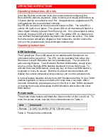
Page 17: ...Q Delay values L Ctrl Home Next Assisted EQ setting L Ctrl PgUp Previous Assisted EQ setting L Ctrl PgDn Increase RED delay R R arrow Decrease RED delay R L arrow Increase Green delay G R arrow Decrease Green delay G L arrow Increase Blue delay B R arrow Decrease Blue delay B L arrow Toggle RED delay L Ctrl R Toggle GREEN delay L Ctrl G Toggle BLUE delay L Ctrl B Reset EQ values L Ctrl End Increas...

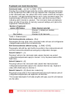
Page 18: ...All channels Table 2 Channel select Exit Command mode and save Esc Pressing the Esc key while in the command mode will save all configuration changes made and exit the command mode Exit Command mode without saving L Shift ESC Pressing the left shift key and the Esc key while in the command mode will exit the command mode without saving any configuration changes Select Channel 1 1 Pressing 1 while ...

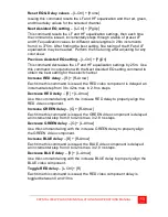
Page 19: ...d to obtain the best setting for the select channel Increase RED delay R R Arrow Each time this command is issued the RED video component is delayed an incremental step from 0 to 42ns max in 2 8 ns steps Decrease RED delay R L Arrow Use this command along with the increase RED delay to properly align the RED video component Increase GREEN delay G R Arrow Each time this command is issued the GREEN ...

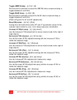
Page 20: ...e right of large objects Decrease LF EQ Course L Dn Arrow Use the Decrease LF EQ adjustment along with the Increase LF EQ to obtain the sharpest image Increase LF EQ Fine L R Arrow Use the Increase LF EQ adjustment to remove black smears to the right of large objects Decrease LF EQ Fine L L Arrow Use the Decrease LF EQ adjustment along with the Increase LF EQ to obtain the sharpest image Increase ...

Page 21: ...le which can inhibit the local unit s monitor When the remote unit issues this command it blanks the monitor and prevents the other unit from being used until the private mode command is issued again To indicate that a unit is in the private mode the scroll lock LED will slowly flash To cancel the private mode enter the Command Mode and press the Scroll Lock key again Local unit Keyboard commands ...

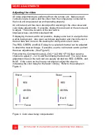
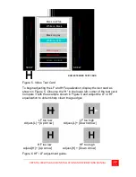
Page 22: ... in a large font on a white background Also open a windows application and check the text in the tool bars and icons on the desktop for clarity and correct colors The RED GREEN and BLUE delay for a selected channel can be adjusted to obtain the clearest image If possible use the on line test card to perform the skew adjustments See Figure 5 First enter the Command mode L Ctrl L Shift F10 then sele...

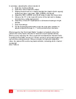
Page 23: ... it with the example shown in Figure 6 and adjust the LF or HF equalization to obtain sharp clean image edges Figure 6 HF LF adjustment guide Black on White White on Black White on Gray Black on gray White on Cyan Yellow on gray Red on gray Red on black Green on black Blue on black SKEW SKEW KVM EXTENDER TEST CARD LF too low LF too high Adjust L Up Arrow Adjust L Down Arrow HF too low HF too high ...

Page 24: ...just the LF and HF Equalization to eliminate smearing or bright streaks 7 Save the settings 8 On the dual and quad models select the next video channel to adjust and perform steps 3 7 on this and all other channels When you enter the Command Mode to adjust a channel s video the yellow LED on the Rj45 connector for channel one will light Not blink When you are adjusting the video keyboard commands ...

Page 25: ...witching The CrystalView Plus USB allows for an additional KVM station to be connected to the Local Unit The CPU can be operated from either the Remote or Local KVM station but not simultaneously The Local Unit is active during boot up To activate the Remote KVM station simply press any key on the Remote KVM stations keyboard or move the mouse To activate the Local KVM station press any key on the...

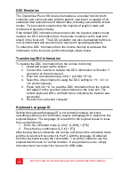
Page 26: ...m 2 Connect the monitor to transfer the DDC information to Monitor 1 connector on the remote unit 3 Enter the command mode L Ctrl L Shift F10 4 Select the video channel to apply the DDC setting to 1 2 or 0 both channels 5 Press left Ctrl D to read the DDC information from the monitor and apply it to the selected video channel on the local unit The remote keyboard LED s will flash twice indicating ...

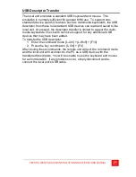
Page 27: ...e descriptor transfer is limited to support for multi media keyboards Check with technical support for any additional USB devices that may have been added To transfer the USB descriptor 1 Enter the command mode L Ctrl L Shift F10 2 Press the key combination L Ctrl F4 After issuing these commands the remote unit will exit the command mode and the local unit will reconnect to the PC as a USB device ...

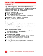
Page 28: ... Improper skew settings adjust color delays Check CATx cable connections No video on remote monitor No power applied to local unit Check USB connection on local unit local unit power is obtained from the CPU USB connection CPUs USB port does not supply adequate power for the local unit Use an external 5V power adapter Monitor goes blank for a few seconds Check CATx cable routing to assure it is no...

Page 29: ... cable loose or defective Audio cable in the wrong connector Sound card Line Out muted No sound at the CPUs speakers when using a Microphone on the Remote Unit Microphone cable in wrong connector Sound card MIC input muted Microphone signal not amplified increase sound card amplification by 20db Add MIC jumper on the Remote Units daughter board to increase signal Do not add this jumper if the micr...

Page 30: ... container or equivalent insured and shipped to Rose Electronics Attn RA__________ 10707 Stancliff Road Houston Texas 77099 USA Technical Support If you are experiencing problems or need assistance in setting up configuring or operating your CrystalView Plus USB consult the appropriate sections of this manual If however you require additional information or assistance please contact the Rose Elect...

Page 31: ...only power cords power adapter and connection cables designed for this Unit Use only a grounded three wire electrical outlet Use only the power adapter provided with the CrystalView Plus USB Keep objects that might damage this Unit and liquids that may spill clear from this Unit Liquids and foreign objects might come in contact with voltage points that could create a risk of fire or electrical sho...

Page 32: ...ION notice until you have understood the hazardous conditions and have taken appropriate steps Grounding These are Safety Class I products and have protective earthing terminals There must be an un interruptible safety earth ground from the main power source to the product s input wiring terminals power cord or supplied power cord set Whenever it is likely that the protection has been impaired dis...

Page 33: ...eps 42ns max per color Mouse Standard PS 2 two three button Standard wheel mice Logitech 3 button PS 2 Console lockout period 2 seconds Serial data Format Transparent Signals TX RX RTS CTS DTR DSR Baud rate 19 2K max Audio data Digitized bi directional stereo audio Input level 4 0 V P P Input impedance 47K ohms Local power From PC USB port optional 5V adapter Remote power 5V 10W Regulated auto sen...

Page 34: ...le video w serial audio Dual video Dual video w serial audio 4 88 124 4 88 124 4 88 124 5 71 145 5 51 144 5 51 144 5 51 144 5 51 144 4 44 113 4 44 113 4 44 113 4 44 113 5 94 151 5 94 151 5 94 151 5 94 151 1 18 30 1 73 44 1 73 44 1 73 44 1 18 30 1 73 44 1 18 30 1 73 44 Shipping Weight Lbs kg Local Unit Remote unit Single video Single video w serial audio Dual video Dual video w serial audio 4 4 2 0...

Page 35: ... Dual video CRV RU1V Remote unit Single video CRV RU2V Remote unit Dual video AUD Audio serial option TFR 05D400FSUB Remote Optional local power supply CAB 08UTPnnn CAT 5 UTP cable CAB D9MFnnn DB9M to DB9F Serial CAB SPMMnnn Mini Phone 3 5mm audio cable RM BR3 Rack Mount shelf nnn length of cable in feet CAT 5 cable available from 25 to 1 000 feet 7 62 300 meters ...

Page 36: ... result in loss of mounting integrity Secure the mounting brackets or the shelf to the rack using the appropriate size bolts nuts and lock washers The following guidelines should be observed when installing a Do not exceed the operating temperature of 0ο C to 40ο C b Do not block power supply vents or restrict airflow c Mechanical loading of the rack should be considered to prevent instability and...

Page 37: ...omputer or KVM switch 3 Connect Local unit to Remote unit with CAT5 CAT5e or CAT6 cable 4 Apply power to all equipment Select video channel to adjust 5 Enter Command Mode then select Channel 1 2 0 all Display Video test card 6 http www rose com htm crvtestcard htm Reset selected channel 7 left Control Home Apply Assisted EQ 8 Left Control Page Up Next Left Control Page Down Previous Adjust Skew 9 ...

Page 38: ...32 CRYSTALVIEW PLUS USB INSTALLATION AND OPERATIONS MANUAL NOTES ...

Page 39: ......

Page 40: ... 103 0014 東京都中央区日本橋蛎殻町 1 16 11 TEL 03 3668 8089 FAX 03 3668 9872 URL http www cybernetech co jp ...

Reviews: