34
ULTRACONSOLE REMOTE 2 INSTALLATION AND OPERATIONS MANUAL
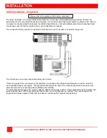
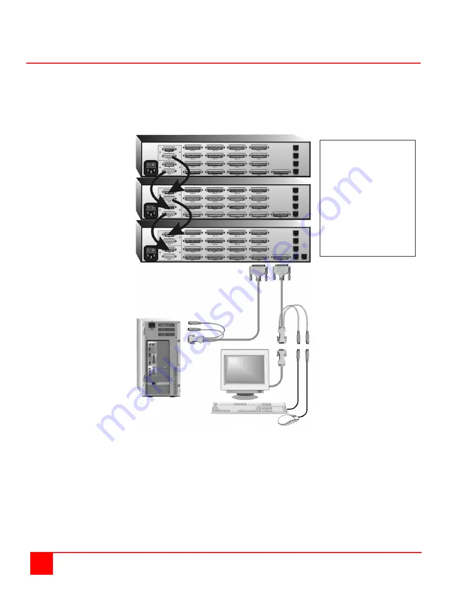
Switch Installation – Multiple units – “BUS” topology
A “BUS” configuration is used when access to all computers is from the main unit #1. In a “BUS” configuration,
(Figure 18) the video path is from the last Unit in the configuration to the first Unit (“OUT” to “IN”). A KVM user on the
first Unit can access all computers on all Units. A user connected to Unit #2 can only access computers on
Unit #2 and Unit #3, etc.
The connection to the network can be done at this time but it is not necessary to install multiple units.
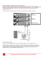
Figure 18. Buss Configuration
The main unit can be any UltraConsole Remote 2 model; other expansion units are UltraConsole units.
The “BUS” installation procedure is very similar to the single Unit installation with the addition of connecting the
expansion cables and changing two configuration parameters, the “Starting computer” number and the “Maximum
computers” number. All Units in the system must have an expansion card(s) with a jumper installed on JP1.
(NOTE: Jumper JP1 is factory installed on all expansion cards)
Unit #3
UltraConsole
Unit #2
UltraConsole
Unit #1 (Main unit)
UltraConsole Remote 2
Summary of Contents for UCR-1R1X16U/2
Page 2: ......
Page 4: ......
Page 67: ......
Page 68: ...10707 Stancliff Road Phone 281 933 7673 Houston Texas 77099 www rose com ...


