


OVERVIEW
Orion XC Installation and Operations Manual
5
System Overview
An Orion XC matrix system consists of an Orion XC matrix, one or more CPU Units, and one or more CON
Units. The Orion XC matrix is connected to the CPU Units / CON Units by CATx interconnect cables.
The CPU units are connected to the computers’ video, keyboard and mouse ports using standard video and
USB or PS/2 cables. CON Units are connected to console display, keyboard, mouse and USB peripherals.
The communication between the Orion XC matrix and the CPU Units / CON Units takes place over CATx
interconnect cables.
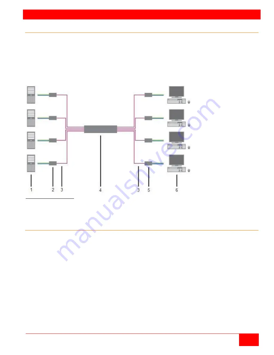
Figure 1. System Overview
1 - Source (computer, CPU)
2 - CPU Units
3 – CATx Interconnect cables
4 - Orion XC matrix
5 - CON Units
6 - Console (monitor, keyboard, mouse)
Synchronized switching
The Orion XC unit can be set up to control the switching features of other Orion XC units. When the
master unit is switched to a selected CPU port, all other Orion XC units configured for synchronization will
also switch to that CPU port. The main unit is assigned a unique IP address compatible with the existing
network. The main unit is then connected to the network via a network cable. The master unit’s IP
address is entered into the secondary units that will be switched via the main unit.


