background image

3. Assembly and Ink Filling

10

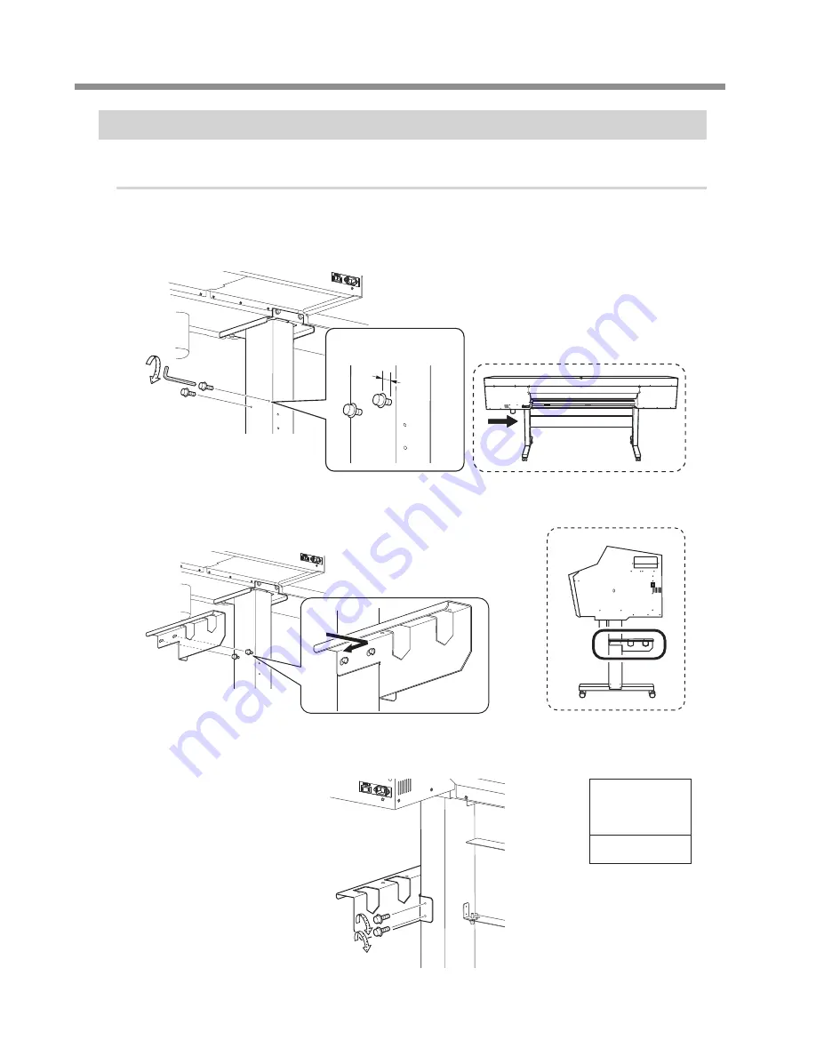
Step 2 : Installing the Media Holders

Procedure

Lightly tighten the bolts on the left side of the stand as seen from the rear of the printer.

Tighten the bolts in the holes on the left side of the stand until you can see approximately 10 mm (0.4 
inches) of their threads.

About 10 mm (0.4 in.)

Rear

Attach the arm to the lightly tightened bolts.

Lightly tighten the bolts connecting the rear of the stand to the arm's contact surface.

Tighten 

temporarily

Bolts: 2

Summary of Contents for TrueVIS VG-540

Page 1: ... of this product are subject to change without notice This manual and the product have been prepared and tested as much as possible If you find any misprints or errors please inform Roland DG Corp Roland DG Corp assumes no responsibility for any direct or indirect loss or damage that may occur through use of this product regardless of any failure to perform on the part of this product Roland DG Co...

Page 2: ......

Page 3: ...etainers 14 Step 5 Adjusting the Ink Tube and Affixing a Label Only When Using Four Colors 15 Step 6 Connecting the Cables 16 Step 7 Initial Settings 17 Step 8 Ink Filling 19 4 Installing the Cutting Tool 26 Step 1 Assembling the Cutting Tool 26 Step 2 Installing the Cutting Tool 27 5 Network Settings 29 Step 1 Make the Network Settings for the Computer 29 Step 2 Make the Network Settings on the P...

Page 4: ...ocation Working in a location that is dark or cluttered may lead to an accident such as becoming caught in the machine as the result of an inadvertent stumble WARNING Position the machine so that the power plug is within immediate reach at all times This is to enable quick disconnection of the power plug in the event of an emer gency Install the machine next to an electrical outlet Also provide en...

Page 5: ...in the figure is required in order to use this machine 1 000 mm 39 4 in 4 500 mm 177 2 in 64 inch model 4 000 mm 157 5 in 54 inch model 3 500 mm 137 8 in 64 inch model 3 000 mm 118 2 in 54 inch model Unit space Work space 2 000 mm 78 7 in During operation Temperature 20 to 32 C 68 to 90 F humidity 35 to 80 RH no condensation During non operation Temperature 5 to 40 C 41 to 104 F humidity 20 to 80 ...

Page 6: ... Tray pad 3 Hexagonal wrench 1 Pipe 1 TR cleaning liquid pouches 2 Blade holder 1 Blade 1 Pin 1 Bolts 40 Washers 22 Replacement blades for separating knife 1 Cable clamp 1 Tweezers 1 Cleaning liquid 1 Cleaning sticks Setup Guide this docu ment 1 Read this first 1 User s Manual 1 Inkjet printer mainte nance guide 1 Cartridge slot label for 4 colors 2 Software RIP 1 The media clamps and the middle p...

Page 7: ...ore Tasks that require undue effort when performed by a small number of persons may result in physical injury Also if dropped such items may cause injury Completed Drawing Necessary Tools Hexagonal wrench large Pipe Use this when the hexagonal wrenches are too small to easily tighten bolts 3 Assembly and Ink Filling ...

Page 8: ...and leg The casters have no particular front and rear orientation Tabletop plate B Lightly tighten the bolts in the 4 upper locations and then in the 4 locations on the sides For the 4 upper locations first tighten the bolts in the narrow slots In this way you can attach the caster in the correct position Use washers in the 4 locations on the sides Tighten temporarily Bolts 8 Washers 4 Narrow Wide...

Page 9: ...and legs parallel to each other and separated by approximately 1 800 mm 70 9 in for the 64 inch model or approximately 1 500 mm 59 1 in for the 54 inch model Position the legs so that the L shaped brackets face the inside and the bent side of the tabletop plate faces down for each leg About 1 800 mm 70 9 in 64 inch model About 1 500 mm 59 1 in 54 inch model Set this part on the bottom F Place the ...

Page 10: ...en the bolts in the order of 1 2 Before tightening the bolts check once more that the 2 stand legs are parallel If the inside of the stand stay is touching the L shaped brackets and the stand legs the stand legs will be parallel When tightening the bolts fully tighten them securely Loose bolts may cause the stand to wobble Tighten fully Bolts 6 Washers 6 ...

Page 11: ... the assembled stand upright and then fix the printer unit to it by tightening the bolts 8 locations in total Use a washer for each bolt Tighten temporarily Bolts 8 Washers 8 J Fully tighten the bolts in the order of 1 2 Tighten the bolts securely Loose bolts may cause the stand to wobble Tighten fully Bolts 8 Washers 8 ...

Page 12: ...rom the rear of the printer Tighten the bolts in the holes on the left side of the stand until you can see approximately 10 mm 0 4 inches of their threads About 10 mm 0 4 in Rear B Attach the arm to the lightly tightened bolts C Lightly tighten the bolts connecting the rear of the stand to the arm s contact surface Tighten temporarily Bolts 2 ...

Page 13: ... Attach the other arm to the right side as seen from the rear of the machine F Place the shafts on the arms G Pass the left media holder onto the shafts Pass it through from the right edge as seen from the rear of the machine Catch the left media holder on the rear shaft Pass the front shaft through the left media holder ...

Page 14: ...ghten the retaining screw I In the same manner pass the right media holder onto the shafts and then tighten the retaining screw J Attach the shaft clamps to secure the shafts in place To ensure the media holders do not get caught in the shaft clamps do not place the media holders too close to the edges ...

Page 15: ... may remain Bottom plug B Install the drain bottle Screw the drain bottle into the hole where the bottom plug was attached Use caution to turn the bottle without applying excessive force Leave the drain bottle attached at all times Only remove the drain bottle when you are disposing of the discharged fluid Unnecessarily removing the drain bottle may lead to the discharged fluid spilling ...

Page 16: ...aulty operation or breakdown may occur when the power is switched on Store the retainers because they are needed again when transporting the machine Procedure A Remove all the retainers indicated by A B C and D A B C D A B C D B Install the retainer indicated by B at the position indicated in the figure for storage Bolt removed in step B ...

Page 17: ...onnecting the Cables About this procedure This procedure must be performed by a suitably qualified service technician Never attempt to perform this procedure yourself CAUTION Leave this work to a suitably qualified worker This procedure includes work near sources of electrical danger and complex assembly work Incorrect work may result in injury and mechanical malfunction Items used in this procedu...

Page 18: ...s instruction may cause the machine to move suddenly resulting in injury WARNING Connect the machine to an electrical outlet that complies with this ma chine s ratings for voltage frequency and current Incorrect voltage or insufficient current may cause fire or electrical shock WARNING Connect the machine to ground This can prevent fire or electrical shock due to current leakage in the event of a ...

Page 19: ...3 Assembly and Ink Filling 17 Step 7 Initial Settings Procedure A Close the front cover B Switch on the main power switch C Open the ink slot cover D Remove all the pouch trays ...

Page 20: ...NU and press the sub power switch G Press or to select the language you want and then press ENTER MENU LANGUAGE ENGLISH H Press or to select the unit of measurement you want for length and then press ENTER LENGTH UNIT mm INCH I Press or to select the unit of measurement you want for temperature and then press ENTER TEMP UNIT C F ...

Page 21: ...chased separately Purchase them from your authorized Roland DG Corp dealer Items used in this procedure Included Items TR cleaning liquid pouches 2 Items separately purchased Ink pouches each color TR cleaning liquid pouches 1 1 Select the ink type A Press or to select the ink type and then press ENTER SELECT INK TYPE TrueVIS 7C SELECT INK TYPE TrueVIS 4C Select Ink Type Cyan C Magenta M Yellow Y ...

Page 22: ... slots and or in the cleaning liquid slot Remove all the pouch trays REMOVE CARTRIDGE 12345678 2 Clean the print heads using TR cleaning liquid A Set the TR cleaning liquid pouch in the pouch tray C L CL Check that the hook has caught Hook B When the screen shown below appears set the pouch tray in which you have set the TR cleaning liquid pouch in the slot whose number is displayed 7 colors CMYKL...

Page 23: ...uch tray into the slot whose number is flashing MEMO When setting the pouch tray When the pouch tray is set correctly the number stops flashing and remains lit SET CL LIQUID 34 SET CL LIQUID 34 Flashing Lit When removing the pouch tray When the pouch tray is removed correctly the number stops flashing and turns off SET CL LIQUID 34 SET CL LIQUID 4 Flashing Off D When the screen shown below appears...

Page 24: ... distress Dispose of discharged fluid properly in accordance with the laws in effect in your locale Discharged fluid is flammable and contains toxic ingredients Never attempt to incinerate discharged fluid or discard it with ordinary trash Also do not dispose of it in sewer systems rivers or streams Doing so may have an adverse impact on the environment F Quickly attach the emptied drain bottle to...

Page 25: ...scharged fluid or ink near an open flame Doing so may cause a fire CAUTION To store discharged fluid temporarily place it in the included drain bottle or in a durable sealed container such as a metal can or polyethylene tank and cap the container tightly Any spillage or vapor leakage may cause a fire an odor or physical distress B Quickly attach the emptied drain bottle to the machine once more C ...

Page 26: ...ARTRIDGE 1 3 5 7 FILLING INK XX XX IMPORTANT Check the color names indicated on the ink slots and the ink pouches to set all the pouch trays in their correct positions Insert the pouch trays as far as they will go The illustration shows the setting of the pouch tray when seven colors are used YE 4 3 YE 3 4 4 Fill the machine with TR cleaning liquid A When the screen shown below appears set the pou...

Page 27: ...scharged fluid to flow out of the tube and spill soiling your hands or the floor WARNING Never place discharged fluid or ink near an open flame Doing so may cause a fire CAUTION To store discharged fluid temporarily place it in the included drain bottle or in a durable sealed container such as a metal can or polyethylene tank and cap the container tightly Any spillage or vapor leakage may cause a ...

Page 28: ...ing in injury CAUTION Never touch the tip of the blade Doing so may result in injury The cutting performance of the blade will also be impaired Step 1 Assembling the Cutting Tool Required items Blade holder Blade Pin Procedure A Insert the pin Insert the pin to the position where its end sticks out about 3 to 5 millimeters Pin B Insert the blade Insert the blade into the hole Tip Blade 4 Installin...

Page 29: ...press several times to display the screen shown below SUB MENU MAINTENANCE D Press once and then press several times to display the screen shown below MAINTENANCE REPLACE KNIFE E Press ENTER The cutting carriage moves to a position where the blade can be replaced F When the following screen is displayed open the front cover OPEN FRONT COVER Preparations are complete when this screen appears FINISH...

Page 30: ...rriage OK Not OK C Tighten the screw D Close the front cover E Press ENTER Important note on the handling and use of the cutting carriage Leave the cutting carriage screw loose when no cutting tool is installed Keeping the screw firmly tightened causes the cutting tool insertion hole to become gradually smaller making installation difficult ...

Page 31: ... settings consult your network administrator Step 1 Make the Network Settings for the Computer Procedure A Log on to Windows as the Administrator or a member of the Administrators group B Windows 10 From the Start menu click Set and then click Network and Internet Click Network and Sharing Center Click Ethernet or Wi Fi Windows 8 1 From the Start menu click PC settings and then click Control Panel...

Page 32: ...cal Area Connection Status dialog box appears If the User Account Control dialog box appears click Continue D Select Internet Protocol Version 4 TCP IPv4 and then click Properties If the Internet Protocol check box is clear select it The Internet Protocol Version 4 TCP IPv4 Properties dialog box appears ...

Page 33: ...k OK in the Internet Protocol Version 4 TCP IPv4 Properties dialog box click Close in the Ethernet Properties dialog box the Local Area Connection Properties dialog box on Windows 7 and then click Close in the Ethernet Status dialog box the Local Area Connection Status dialog box on Windows 7 Step 2 Make the Network Settings on the Printer 1 Set the IP address A Press MENU B Press several times to...

Page 34: ...as the setting of your computer Here 192 168 000 003 is entered by way of example IP ADDRESS 192 168 000 003 H When you have finished making the setting press ENTER I Press to go back to the screen shown below NETWORK IP ADDRESS 2 Set the subnet mask A Press to display the screen shown below NETWORK SUBNET MASK B Press twice to display the screen shown below SUBNET MASK 000 000 000 000 C Press or ...

Page 35: ...eed to set the gateway address proceed to the following procedure 3 Set the gateway address A Press to display the screen shown below NETWORK GATEWAY ADDR B Press twice to display the screen shown below GATEWAY ADDR 000 000 000 000 C Press or to select the address number D Press E Repeat C and D to set GATEWAY ADDR to 255 255 255 255 Forthevaluetoenterforthegatewayaddress consultyournetworkadminis...

Page 36: ...e software RIP Confirming that a network connection has been established Roland VersaWorks Dual hereinafter referred to as VersaWorks Dual You can use the printing test feature to check whether the connection to the network has been established For information about how to carry out a printing test refer to the documentation for VersaWorks Dual Other software RIP Refer to the documentation for the...

Page 37: ......

Page 38: ......

Reviews: