background image

Cust
omizing a K

it

Customizing a Kit

45

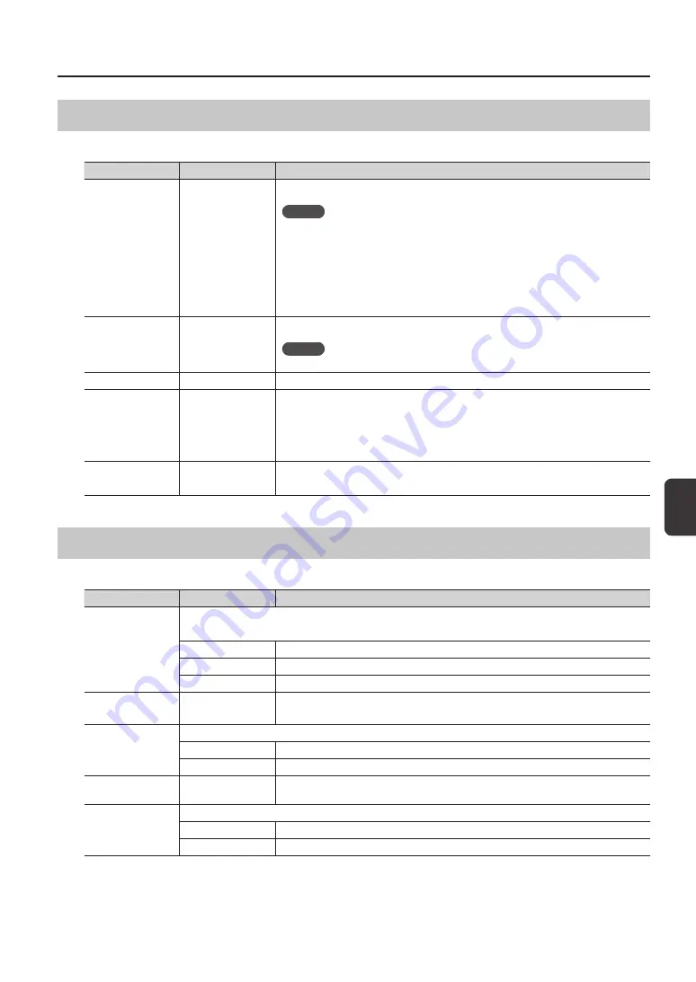
Selecting the Wave Played by a Pad (MAIN)

Here you can make basic settings such as selecting the wave played by a pad and specifying its volume.

Parameter

Value

Explanation

WAVE

00001–10000

Selects the wave played by the pad.

MEMO

• 

The SPD-SX contains preload waves.

• 

The preload waves are also stored on the supplied CD-ROM. If you want to make use of 

the preload waves that came with the unit when it left the factory, load waves from a USB 

flash drive or your personal computer (p. 39).

• 

Waves can also be selected from the WAVE LIST of the quick menu.

• 

By holding down the [PAD CHECK] button and using the [-] [+] buttons you can select the 

wave in steps of 10.

VOLUME

0–100

Adjusts the volume of the pad.

MEMO

You can also set the VOLUME from the top screen (p. 26).

PAN

L15–CENTER–R15

Adjusts the stereo position (left/right balance) of the sound.

MUTE GROUP

OFF, 1–9

Pads for which the same number is specified here will belong to the same mute group. A 

newly played pad will silence any previously sounding pad that belongs to the same mute 

group; only the most recently played pad in the mute group will be heard.
Specify the same mute group for pads that should not be heard together.

*  The pad indicator of all pads in the same mute group will light.

TEMPO SYNC

OFF, ON

If this is “ON,” the wave’s playback speed will change according to the performance tempo.

*  Drastic changes in playback speed may affect the quality of the sound.

Specifying How the Wave is Sounded (MODE)

Here you can specify how the wave will be sounded.

Parameter

Value

Explanation

TEMPLATE

Specifies how the wave will be sounded.

*  If you set TEMPLATE, the MODE parameters will be set to suitable values.

SINGLE

Choose this for sounds used to play single notes, such as percussion sounds.

PHRASE

Choose this for phrases that have a tempo.

LOOP

Choose this when you want the wave to sound repeatedly.

LOOP

OFF, ON, x2, x4, x8

Specifies the number of times that the wave will be repeated.
If this is “ON,” the wave will continue repeating.

TRIG TYPE

Specifies how the wave will play when you play the pad.

SHOT

The wave will play each time you play the pad.

ALT

The wave will alternately play or stop each time you play the pad.

DYNAMICS

OFF, ON

Set it to “ON” to change the volume according to playing velocity. When it is set to “OFF,” the 

sound is produced at a constant volume.

POLY/MONO

Specifies whether the wave will play polyphonically or monophonically.

MONO

Repeated plays will silence the previous sound.

POLY

Repeated plays will be layered on the previous sound.

Summary of Contents for SPD-SX

Page 1: ......

Page 2: ......

Page 3: ...ully read the sections entitled USING THE UNIT SAFELY p 75 and IMPORTANT NOTES p 74 These sections provide important information concerning the proper operation of the unit Additionally in order to fe...

Page 4: ...is easy just connect a microphone or audio source You can also re sample onboard sounds by performing on the SPD SX Vast performance possibilities with diverse sounds The SPD SX comes loaded with a r...

Page 5: ...two footswitches You can customize a kit by assigning the desired wave to each pad selecting the effect to be used in that kit and specifying how they will be played p 42 The SPD SX contains 100 kits...

Page 6: ...nd a KIT FX processor p 23 which can be used on a per kit basis Use these effects to modify and personalize the sounds as appropriate for the song or performance MASTER EFFECT KIT FX Audio signal flow...

Page 7: ...od that s best for your situation p 34 p 32 p 29 Record your performance on the SPD SX p 38 p 36 p 35 Combine two waves into one Sample successively to different pads Sample to one pad Cut a wave Chop...

Page 8: ...mbining Two Waves into One MERGE 34 Resampling with Effects WITH FX 35 Dividing a Wave CHOP 36 Recording the Sound of an SPD SX Performance PERFORM RECORD 38 Importing Audio Files 39 Importing Audio F...

Page 9: ...SENS 60 External Pad Settings TRIG IN 62 Footswitch Settings FOOT SW 63 MIDI Settings MIDI 63 Other Settings OPTION 63 Initializing the Setup Parameters SETUP INIT 64 Other Convenient Functions UTILI...

Page 10: ...Top Panel 10 Panel Descriptions 1 9 10 12 11 13 3 2 14 4 5 6 8 7...

Page 11: ...the F1 F2 and F3 buttons 7 KIT button Displays the top screen p 21 MENU button Accesses various functions such as overall settings for the entire SPD SX p 16 SAMPLING button Captures a sample p 28 QU...

Page 12: ...avoid applying undue stress to the DC IN jack anchor the power cord using the cord hook as shown in the illustration NOTE To prevent malfunction and or damage to speakers or other devices always turn...

Page 13: ...to control a variety of things p 27 p 57 TRIG IN jacks External pads PD series sold separately or acoustic drum triggers RT series sold separately can be connected here p 27 To make the connection us...

Page 14: ...u want to attach the SPD SX to a cymbal stand and play it in conjunction with V Drums or a drum set secure it using an all purpose clamp APC 33 sold separately Use the screws on the bottom panel of th...

Page 15: ...laying or operating the unit If you don t want the power to turn off automatically change the AUTO OFF setting to OFF as described on p 63 If AUTO OFF is set to 4hrs the message AUTO OFF is set to 4h...

Page 16: ...ake settings for the kit effects p 46 SYS SYSTEM Make overall sound and performance settings for the entire SPD SX p 53 SETUP Make overall display pad and MIDI related settings for the entire SPD SX p...

Page 17: ...esired you can make settings so that a pad will not be selected for editing when you play it p 63 Pressing the EXIT button will take you back to the previous screen 5 When you ve finished making setti...

Page 18: ...les from the USB flash drive p 39 Use the USB flash drive to save or load the SPD SX s waves or settings p 65 p 66 1 Connect your USB flash drive to the USB MEMORY connector USB flash drive Carefully...

Page 19: ...er is provided on the included CD ROM For the operating requirements refer to ReadmeEN txt on the CD ROM The procedure for installing the USB driver will depend on the system you re using so carefully...

Page 20: ...d 6 Pad 9 Pad 5 Example When you play pad 7 Pad indicator 7 will light Stopping All Sounds Here s how to stop all currently playing sounds 1 To stop all sounds press the ALL SOUND OFF button MEMO You...

Page 21: ...button and pressing the button or by holding down the button and pressing the button You can register the order in which you want to switch kits This is called a path Chain p 56 You can freely customi...

Page 22: ...AL CTRL Turn VISUAL CTRL SW on off p 57 LCD LED Jump to the LCD LED screen p 59 Using the Master Effects Try using a master effect p 6 which will affect all sounds in the current kit 1 Play the pads t...

Page 23: ...ange the frequency response or vary the effect s depth Applying a Kit Effect KIT FX SW Try applying a kit effect p 6 to your performance If you want to output the sound processed by the kit effect set...

Page 24: ...will light A click will sound at the tempo and the TEMPO indicator will blink 2 Turn the CLICK knob to adjust the volume of the click sound MEMO You can change the type of click sound p 54 Settings fo...

Page 25: ...he tempo F1 TAP button Specify the tempo by repeatedly pressing the button at the desired timing 3 Press the F3 X button to return to the top screen MEMO You can use the KIT TEMPO p 42 setting to spec...

Page 26: ...the top screen press the F1 PADVOL button 2 Use the cursor buttons to select the pad whose volume you want to adjust and use the buttons to adjust its volume MEMO You can also use the VOLUME p 45 set...

Page 27: ...switch press the footswitch 7 Specify the wave and volume p 44 MEMO Instead of using an external pad or footswitch to play sounds you can also use it to change kits or turn a kit effect on off p 57 FO...

Page 28: ...tely 360 minutes of monaural sound into internal memory including the preload waves MEMO You can check the sampling time that remains p 66 The amount of time over which sampling can take place at one...

Page 29: ...TER connector to your computer p 19 2 Set the input level appropriately for the device that s connected Microphone Computer Digital audio player etc Set the GAIN knob on the rear panel to the MIC posi...

Page 30: ...ve will be assigned You can only select an empty pad one which has no wave assigned to it Signal flow AUDIO IN jacks REC LEVEL GAIN knob Analog signal Digital signal Level meter Adjust to avoid the le...

Page 31: ...se the buttons to make adjustments This region will sound Start point End point F3 END button Adjusts the end point the point at which the wave stops sounding Use the buttons to make adjustments If yo...

Page 32: ...ULTI and press the ENTER button The sampling setup screen will appear 5 Use the cursor buttons and the buttons to make settings for sampling Parameter Value Explanation REC LEVEL 0 100 Adjusts the vol...

Page 33: ...xt The screen will indicate the status of each pad Pad is being sampled Pad for which sampling is complete Unassigned pad MEMO Sampling to that pad will stop when you press the ENTER button or when yo...

Page 34: ...tons and the buttons to make settings for sampling Parameter Value Explanation SOURCE KIT001 100 PAD1 9 From a single kit select the two waves that you want to combine KIT001 100 PAD1 9 Select the kit...

Page 35: ...t that is selected for SOURCE will be applied KIT001 100 PAD1 9 Select the kit and pad to which the wave you ve applied effects to is to be assigned You can only select an empty pad one which has no w...

Page 36: ...Use the cursor buttons and the buttons to make settings for sampling Parameter Value Explanation SOURCE KIT001 100 PAD1 9 Select the original wave that you want to chop KIT001 100 Select the kit to w...

Page 37: ...mpling to the first pad will stop and sampling to the pad you struck will begin MEMO Sampling to that pad will stop when you press the ENTER button or when you once again play the pad that s being sam...

Page 38: ...001 100 Select the kit and pad to which the recorded performance is to be assigned You can only select an empty pad one which has no wave assigned to it REC LEVEL 0 100 Adjust the volume for sampling...

Page 39: ...top level of your USB flash drive 2 Connect your USB flash drive to the SPD SX s USB MEMORY connector p 18 3 Choose MENU UTILITY WAVE IMPORT The WAVE IMPORT screen will appear 4 Use the cursor buttons...

Page 40: ...f internal memory and the remaining amount of time for sampling Importing Audio Files fromYour Computer By using SPD SX Wave Manager provided on the included CD ROM audio files from your computer can...

Page 41: ...audio files into the SPD SX Importing waves into the SPD SX Drag and drop a WAV file or AIFF file into the wave list Click this to exit SPD SX Wave Manager If you are going to operate the SPD SX after...

Page 42: ...ngs of the selected parameter for all pads PAD LOCK Turn PAD LOCK on off p 63 SET ALL PAD Copies a parameter setting to all pads p 47 PAD COPY Copies a pad p 48 PAD PASTE Pastes a pad p 48 PAD EXCHANG...

Page 43: ...back continues for an extended period of time Setting the kit tempo based on the wave tempo Here s how to set the kit s tempo KIT TEMPO according to the wave tempo setting 1 Play a pad to select a wav...

Page 44: ...planation Page MULTI VIEW Lists the settings of the selected parameter for all pads PAD LOCK Turns PAD LOCK on off p 63 SET ALL PAD Copies a parameter setting to all pads p 47 PAD COPY Copies a pad p...

Page 45: ...pads that should not be heard together The pad indicator of all pads in the same mute group will light TEMPO SYNC OFF ON If this is ON the wave s playback speed will change according to the performanc...

Page 46: ...ording to the following settings Parameter Value Parameter Value MUTE GROUP Same setting as MAIN p 45 TRIG TYPE OFF TEMPO SYNC OFF DYNAMICS Same setting as MAIN p 45 LOOP OFF POLY MONO MONO Applying a...

Page 47: ...screen will also appear for other quick Menu items WAVE NAME p 64 CHAIN NAME p 56 2 Enter the name Button Explanation buttons Change characters Cursor buttons Move the cursor to the character you want...

Page 48: ...s the EXIT button 7 Press the ENTER button once again The kit will be pasted Copying Pasting a Pad This operation copies the settings of the last struck pad allowing you to paste them to a different p...

Page 49: ...lost when you execute KIT INIT If you want to keep the settings save them to a USB flash drive before you continue p 66 1 Select the kit that you want to initialize p 21 2 In the KIT screen or the FX...

Page 50: ...t the wave that you want to edit p 44 2 Choose QUICK MENU WAVE NORMALIZE 3 Select the save destination wave Button Explanation ENTER button Save as a new wave F3 OVER WRITE button Save by overwriting...

Page 51: ...is region will sound Start point End point WAVE TRUNCATE 1 Specify the start point and end point of the wave that you want to edit p 50 2 In the KIT PAD screen choose QUICK MENU WAVE TRUNCATE 3 Select...

Page 52: ...LIST screen select the wave that you want to copy p 64 2 Choose QUICK MENU WAVE COPY 3 Press the ENTER button The wave will be copied Deleting aWave WAVE DELETE Here s how to delete a wave 1 In the WA...

Page 53: ...gs of the SYSTEM parameters p 58 Master Effect Settings MASTER EFFECT Here you can select the master effect types Press one of the master effect buttons to select the master effect for which you want...

Page 54: ...EP OLD STYLE DRUM STICKS MARCHING SNARE CLAVES COWBELL SHAKER Select the type of click sound WAVE Select a click sound from among the user waves INTERVAL 1 4 1 8 1 12 Select the interval for the click...

Page 55: ...e jack s from which the audio arriving at AUDIO IN jacks will be output MASTER Output from the MASTER OUT jacks and the PHONES jack SUB OUT Output from the SUB OUT jacks and the PHONES jack PHONES Out...

Page 56: ...Choose MENU SYSTEM KIT CHAIN The KIT CHAIN screen will appear Use the cursor buttons and the buttons to specify the kit chain Use the buttons to turn the kit chain function on off Use the buttons to...

Page 57: ...trol is a function that lets you control images along with your performance The SPD SX lets you do the following when a video device supporting MIDI Visual Control or V LINK is connected Switch kits i...

Page 58: ...the CONTROL 2 knob will transmit a control change message MEMO If the Visual Control function is on the VISUAL CONTROL icon is shown in the top screen For details on how to switch between images refer...

Page 59: ...he brightness of the display and specify how the indicators will light Parameter Value Explanation LCD CONTRAST 1 10 Adjusts the contrast of the display LCD BRIGHT 1 10 Adjusts the brightness of the d...

Page 60: ...when the pad is struck lightly Gradually raise the THRESHOLD value while striking the pad Check this and adjust accordingly Repeat this process until you get the perfect setting for your playing styl...

Page 61: ...in and prevents re triggering from occurring While repeatedly striking the pad raise the RETRIG CANCEL value until re triggering no longer occurs Time Although setting this to a high value prevents re...

Page 62: ...volume even when played softly Lower value will keep the rim edge producing a low volume even when played forcefully RIM ADJUST 0 0 8 0 When a PD 125 120 105 85 80R PDX 8 or RT 10S is connected you c...

Page 63: ...his is ON playing a pad in the KIT PAD screen p 44 will not select the pad for editing This is convenient when you want to check the sound of other pads while you edit AUTO OFF OFF 4hrs The SPD SX has...

Page 64: ...UTILITY WAVE LIST The WAVE LIST screen will appear Wave name Wave number 2 Use the cursor buttons to view the waves MEMO You can use the quick menu to choose how the waves are displayed for example by...

Page 65: ...MENU UTILITY LOAD USB MEM The LOAD USB MEMORY screen will appear 3 Use the cursor buttons to select the command that you want to execute and then press the ENTER button Item Explanation KIT SETTINGS K...

Page 66: ...tton If you want to create newly saved data choose SAVE AS If you want to overwrite previously saved data select the data that you want to overwrite If you selected the previously saved data proceed t...

Page 67: ...at you want to set 3 Edit the parameter Parameter Value Explanation PAD CH GLOBAL 1 16 Allows you to set the channel on which transmission reception takes place on an individual pad basis When set to...

Page 68: ...he perfor mance data will not be sent directly to the SPD SX s internal sound generator but will be routed through the external sequencer and then sent back to the SPD SX SOFT THRU OFF ON If this is O...

Page 69: ...t sound Could the level of the wave or sub wave be lowered Adjust the level of the wave or sub wave p 45 p 46 Have the settings for OUTPUT been made correctly Check the settings for OUTPUT p 43 Have...

Page 70: ...able to process them all Make sure that the external MIDI device is correctly connected If this does not solve the problem decrease the amount of MIDI messages being transmitted to the SPD SX MIDI OFF...

Page 71: ...nch phone type AUDIO IN jacks L MONO R 1 4 inch phone type with LINE MIC GAIN control TRIG IN jacks 1 2 3 4 1 4 inch TRS phone type FOOT SW jack 1 2 1 4 inch TRS phone type MIDI connectors IN OUT DC I...

Page 72: ...ch 13 27 FOOT SW jack 13 27 FS1 POLARITY 63 FS2 POLARITY 63 Function buttons 11 FX2 55 FX button 11 22 G GAIN knob 13 GATE 67 GLOBAL CH 68 H Headphones 13 HIGH GAIN 55 I INFORMATION 66 Initialize Kit...

Page 73: ...EMORY 66 SCAN TIME 61 SERIAL NO 66 SET ALL PAD 47 SETUP 54 59 SETUP INIT 64 S LOOP button 11 22 SOFT THRU 68 SOUND 54 SOUND GROUP 54 SPD SX Wave Manager 19 40 Stand 14 START STOP button 11 24 SUB 46 S...

Page 74: ...sembled About WARNING and CAUTION Notices About the Symbols ALWAYS OBSERVE THE FOLLOWING WARNING Do not open or modify in any way the unit or its AC adaptor Do not attempt to repair the unit or replac...

Page 75: ...rate electrical outlet connect a power supply noise filter between this unit and the electrical outlet The AC adaptor will begin to generate heat after long hours of consecutive use This is normal and...

Page 76: ...ld typically be shown by the display Note however that your unit may incorporate a newer enhanced version of the system e g includes newer sounds so what you actually see in the display may not always...

Page 77: ...cause harmful interference to radio or television reception which can be determined by turning the equipment off and on the user is encouraged to try to correct the interference by one or more of the...

Page 78: ...78 For EU Countries SJ T GB T GB T Pb Hg Cd Cr VI PBB PBDE...

Page 79: ......

Page 80: ......

Reviews: