- 38 -
BIOS
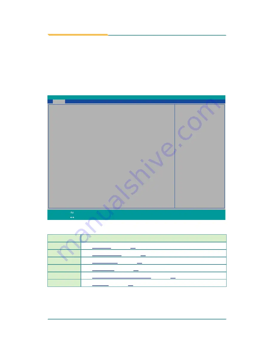
The BIOS Setup utility for the computer is featured by American Megatrends
Inc to configure the system settings stored in the system’s BIOS ROM. The
BIOS is activated once the computer powers on. When the computer is off, the
battery on the main board supplies power to BIOS RAM.
To enter the BIOS Setup utility, keep hitting the “Esc” key upon powering on
the computer.
InsydeH20 Setup Utility
Rev. 5.0
BIOS
Version
R0.05
System Date
System Time
[17:04:19]
[03/17/2014]
Language
<English>
Set the current default language
used by the InsydeH2O.
Advanced Security
Power
Boot Exit
Main
Project
Name
ARES-5300
Build
Date
02/25/2014
Build
Time
10:16:18
Platform firmware information
VLV
SOC
OC
(B3
Stepping)
MRC
Version
0.95
PUNIT
FW
0x2D
KSC
FW N/A
PMC
FW
Patch
0x3_18
TXE
FW
Version
1.1.0.10x89
IGD
VBIOS
Version
1007
Microcode
Revision
320
CPU
Flavor
VLV
Desktop
(2)
Board
ID
BALEY
BAY
(20)
Fab
ID
FAB3
(03)
Processor
Intel(R)
Celeron(R)
CPU
J1900
@1.99GHz
System
Bus
Speed
83
MHz
System Memory Speed
1333 MHz
Cache
RAM
1024
KB
Total
Memory
2048
MB
Channal
A
SODIMM0
2048
MB
SODIMM1
[Not
Installed]
Channal B
SODIMM0
[Not
Installed]
SODIMM1
[Not
Installed]
Change Values
F5/F6
Select
SubMenu
Enter
Select Item
Select Menu
F1
Exit
ESC
Help
Setup Defaults
F9
Save and Exit
F10
The BIOS featured menus are:
Menu
Description
Main
See
5.1. Main
on page
40
.
Advanced
See
5.2. Advanced
on page
41
.
Security
See
5.3. Security
on page
47
.
Power
See
5.4. Power
on page
48
.
Boot
See
5.4.1 Advanced CPU Control
on page
49
.
Exit
See
5.6. Exit
on page
53
.
Summary of Contents for ARES-5300
Page 2: ... 2 This page is intentionally left blank ...
Page 3: ... i Revision History Version Date Description 1 0 March 2014 Initial release ...
Page 6: ... iv This page is intentionally left blank ...
Page 12: ... x This page is intentionally left blank ...
Page 13: ... 1 1 Chapter 1 Introduction Chapter 1 Introduction ...
Page 18: ... 6 This page is intentionally left blank ...
Page 19: ... 7 2 Chapter 2 Getting Started Chapter 2 Getting Started ...
Page 22: ... 10 Getting Started Side View DC in power jack Rear View DIN rail clip ...
Page 25: ... 13 3 Chapter 3 System Configuration Chapter 3 System Configuration ...
Page 30: ... 18 System Configuration Front Panel ...
Page 36: ... 24 This page is intentionally left blank ...
Page 37: ... 25 4 Chapter 4 Installation and Maintenance Chapter 4 Installation and Maintenance ...
Page 48: ... 36 This page is intentionally left blank ...
Page 49: ... 37 5 Chapter 5 BIOS Chapter 5 BIOS ...
Page 66: ... 54 This page is intentionally left blank ...
Page 67: ... 55 Appendices Appendices ...


