background image


145 / 191   - NL - 

4.


Gebruik 


4.1.


Doelmatig gebruik 


De kleisnijder TS 20 is bedoeld voor het opwerken en homogeniseren van klei en porseleinmassa’s.  


Daarnaast is het apparaat geschikt om verschillende soorten klei met elkaar te vermengen of chamotte bij te 

mengen. 


Het apparaat is niet geschikt om kleimeel met water op te werken of klei te maken. Daarvoor is een 

gesloten systeem nodig, bijvoorbeeld een inweekbak of een kneder. 


Het apparaat mag alleen doelmatig worden gebruikt in de zin van de gebruiksaanwijzing.  


Het apparaat mag niet anders worden gebruikt dan hierboven beschreven. 


Alle aanwijzingen en veiligheidsvoorschriften in de gebruiksaanwijzing moeten worden opgevolgd. 


Alle veiligheidsinstructies die op het apparaat zijn aangebracht, moeten worden opgevolgd. 


Het apparaat mag alleen worden bediend door geschoold of geïnstrueerd personeel.  


Kinderen en jongeren onder de 18 jaar mogen het apparaat niet bedienen resp. gebruiken. 


Personen met een lichamelijke of verstandelijke beperking mogen het apparaat niet bedienen resp. 

gebruiken. 


Personen die lichamelijk beperkt zijn door ziekte, medicatie of na alcoholconsumptie 

mogen het apparaat niet bedienen. 


Het apparaat mag alleen doelmatig zoals geleverd worden gebruikt. Wijzigingen of aanpassingen achteraf 

door de gebruiker resp. exploitant zijn niet toegestaan en maken een doelmatig gebruik zoals bedoeld door 
de fabrikant onmogelijk. 


4.2.


Redelijkerwijs te verwachten verkeerd gebruik 


Inzet van onvoldoende geïnstrueerd en gekwalificeerd personeel 


Gebruik van ongeschikte materialen 


Gebruik van gezondheidsbedreigende stoffen die in gevaarlijke concentraties vrijkomen 


Gebruik van vervangende en slijtonderdelen die niet zijn vrijgegeven 


Gebruik van verbruiks-, reinigings- en overige middelen die niet zijn vrijgegeven 


Opstelling op een ongeschikte plek 


Niet nakomen van de aanbevolen onderhoudsfrequenties resp. verkeerd uitgevoerd onderhoud 


Verzuim van noodzakelijke reparaties 


Verzuim van noodzakelijke reinigingswerkzaamheden 


5.


Levering 


5.1.


Levering controleren 

De kleisnijder wordt normaal gesproken door een koeriersbedrijf geleverd. Controleer bij levering altijd onmiddellijk of 

de verpakking zichtbaar beschadigd is. Indien dit het geval is, pakt u het apparaat samen met de chauffeur uit en 
controleert u het nogmaals nauwkeurig op beschadigingen. Noteer eventuele beschadigingen direct op het 

leveringsbewijs en maak zo nodig foto’s. Laat de chauffeur van het transportbedrijf altijd het leveringsbewijs met de 
gedocumenteerde beschadigingen medeondertekenen. Bewaar een kopie van de schadeclaim. Meld de schade 
ook onmiddellijk aan het transportbedrijf. Een schadeclaim indienen op een later tijdstip is niet mogelijk. 


5.2.


Apparaat uitpakken 

Verwijder altijd alle verpakkingsmaterialen. 


Summary of Contents for TS 20

Page 1: ...nstructions Pugmill TS 20 Notice d utilisation originale Boudineuse TS 20 Manual de instrucciones original Cortador de arcilla TS 20 Istruzioni per l uso originali Impastatrice TS 20 Originele gebruiksaanwijzing Kleisnijder TS 20 Původní návod k provozu Mísiče hlíny TS 20 ...

Page 2: ...yky Deutsch Originalbetriebsanleitung Tonschneider TS 20 ab Seite 1 English Original Operating Instructions Pugmill TS 20 1 from page 29 Français Notice d utilisation originale de boudineuse TS 20 2 de la page 56 Español Manual de instrucciones original del cortador de arcilla TS 20 3 de la página 84 Italiano Istruzioni per l uso originali impastatrice TS 20 4 da pagina 111 Nederlands Originele ge...

Page 3: ...ungsgemäße Verwendung 8 4 2 Vernünftigerweise vorhersehbare Fehlanwendungen 9 5 Anlieferung 9 5 1 Lieferung prüfen 9 5 2 Gerät auspacken 9 5 3 Verpackung entsorgen 9 6 Aufstellung Montage 10 6 1 Allgemeiner Sicherheitshinweis 10 6 2 Allgemeine Aufstellhinweise 10 6 3 Transport 10 6 4 Montage Arbeitstisch 11 6 4 1 Allgemeiner Sicherheitshinweis 11 6 4 2 Montage 11 7 Inbetriebnahme 12 7 1 Hinweise S...

Page 4: ...che Komponenten 20 11 4 Werkskundendienst 20 11 5 Wartungsvertrag 20 12 Instandhaltung 20 12 1 Allgemeine Sicherheitshinweise 20 12 2 Ersatz Verschleißteile 21 12 3 Anzugsdrehmomente 21 12 4 Ölwechsel am Antriebsmotor 21 12 4 1 Allgemeine Beschreibung 21 12 4 2 Allgemeine Sicherheitshinweise 21 12 4 3 Benötigtes Öl 22 12 4 4 Beschreibung 22 13 Störung 24 13 1 Allgemeine Sicherheitshinweise 24 13 2...

Page 5: ...lle weiteren Maschinenkomponenten welche mit Ton in Kontakt kommen sind aus nichtrostendem Edelstahl gefertigt Die stehende Ausführung und die große Einfüllöffnung ermöglichen eine bequeme Beschickung des Tonschneiders von oben Zum Reinigen lässt sich der Mischzylinder problemlos zerlegen Zwei Transportrollen und zwei fest montierte Maschinenfüße gewährleisten Mobilität und sicheren Stand Der Arbe...

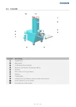
Page 6: ...rtioniereinrichtung Abschneidevorrichtung 4 Mundstück Materialausgabe 5 Arbeitstisch 6 roter Taster zum Ausschalten 7 Netzkabel 8 Feinsicherung 9 Handgriff an der Geräterückseite nicht sichtbar 10 grüner Taster zum Einschalten 11 Materialzugabe in Mischzylinder 1 2 3 4 5 6 7 8 9 10 11 ...

Page 7: ...ng jeweils vor der Beschreibung von potenziell gefährlichen Arbeitsschritten aufgeführt 3 1 2 Arten aufgeführter sicherheitsbezogener Hinweise GEFAHR Das Symbol mit Signalwort bezeichnet eine unmittelbar drohende Gefahr Wenn sie nicht gemieden wird sind Tod oder schwerste Verletzungen die Folge WARNUNG Das Symbol mit Signalwort bezeichnet eine möglicherweise drohende Gefahr Wenn sie nicht gemieden...

Page 8: ... Elektrofachkräften durchführen Lassen Sie alle weiteren Arbeiten nur von qualifiziertem Personal vornehmen GEFAHR Vor Personen und Sachschäden Aus Sicherheitsgründen muss vor allen Arbeiten am Gerät der Netzstecker aus der Steckdose gezogen werden WARNUNG Vor Personen und Sachschäden Der Transport und die Montage des Tonschneiders sollten auf Grund des hohen Eigengewichts von mindestens 2 Persone...

Page 9: ...ift 3 oder entsprechender nationaler Vorschrift des Betreiberlandes zu prüfen 3 6 Schutzeinrichtungen 3 6 1 Allgemeiner Sicherheitshinweis GEFAHR Von Personen und Sachschäden Beachten Sie dass der Betrieb des Geräts nur mit funktionsfähigen Schutzeinrichtungen zulässig ist Das Entfernen Verändern oder Umgehen der Schutzeinrichtungen ist verboten Der Betrieb ohne funktionsfähige Schutzeinrichtungen...

Page 10: ...keramische Massen miteinander mischen oder sogenannte Schamotte einmischen Das Gerät ist nicht dafür geeignet um Tonmehle mit Wasser aufzubereiten oder um keramische Massen zu erzeugen Dazu wird ein geschlossenes System wie ein sogenanntes Einsumpfbecken oder ein Knetmischer benötigt Das Gerät darf nur bestimmungsgemäß im Sinne der Betriebsanleitung verwendet werden Das Gerät darf nicht über die z...

Page 11: ...ter geliefert Die Sendung ist in jedem Fall bei der Anlieferung sofort auf sichtbare Beschädigungen der Verpackung zu prüfen Sollte dies der Fall sein packen Sie das Gerät umgehend in Anwesenheit des Fahrers aus und prüfen Sie die Ware im Detail auf Beschädigungen Fotografieren Sie eventuelle Schäden und dokumentieren Sie diese sofort auf dem Lieferschein Lassen Sie unbedingt den Fahrer die dokume...

Page 12: ... das Gerät auf eine ebene Fläche Sorgen Sie für einen sicheren Stand auf einem festen Untergrund Der Abstand zu Wänden anderen Geräten und Verkehrswegen sollte an allen Seiten mindestens 10cm betragen 6 3 Transport Transportieren Sie den Tonschneider aufrechtstehend auf der Originalpalette Benutzen Sie Ladungssicherungen zur Verbringung des Geräts Zur weiteren Verbringung ohne Palette das Gerät am...

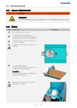
Page 13: ...Palette 2 Der Arbeitstisch ist bei Anlieferung am Mischzylinder mit Spannbändern befestigt Nehmen Sie den Arbeitstisch vom Mischzylinder ab 3 Entfernen Sie weitere Verpackungsteile sofern noch vorhanden 4 Entfernen Sie die Befestigungsschrauben für den Arbeitstisch 5 Halten Sie den Arbeitstisch mit seinen Befestigungspunkten an die Position wo vorher die Schrauben entfernt wurden Hinweis Die Monta...

Page 14: ...l mit dem Stecker in den passend vorbereiteten Stromanschluss am Aufstellort Es darf kein Verlängerungskabel verwendet werden 7 2 2 Hinweis zur Drehrichtung nur TS 20 mit 400 V 8 Betrieb 8 1 Allgemeine Sicherheitshinweise GEFAHR Verletzungsgefahr Warnung vor rotierenden Bauteilen Es ist strengstens verboten bei laufendem Betrieb in den Mischzylinder zu fassen Wenn der Tonschneider mit einem 400V A...

Page 15: ...s zu schalten 8 3 NOT AUS Betätigen Sie bei Not und Zwischenfällen mit dem Gerät die entsprechenden Haussicherung für den Stromkreis an welchem der Tonschneider angeschlossen ist 8 4 Hinweis zur Betriebsdauer Das Getriebeöl des Antriebsmotors muss in regelmäßigen Abständen von 4000 Betriebsstunden oder spätestens nach 4 Jahren gewechselt werden Hinweis Vermerken Sie während der Benutzung die Betri...

Page 16: ...nd Dichtungen beschädigt werden 9 2 2 Beschreibung Schritt Tätigkeit 1 Den Ton in handlichen Größen von oben in den Mischzylinder einfüllen 2 Der Ton wird schnell durch die Mischmesser nach unten befördert 3 Achten Sie darauf dass der Mischzylinder fortlaufend gut gefüllt ist 4 Dadurch kann der Tonschneider optimal mischen und entlüften 5 Gleichzeitig wird bei guter Füllung der größte Durchsatz pr...

Page 17: ...ten am Gerät entweder mit Warntafeln oder Absperrungen Das Gerät darf währenddessen nicht in Betrieb genommen werden An der Materialausgabe Mundstück des Tonschneiders befindet sich eine Abschneidevorrichtung Portioniereinrichtung zum Ablängen des verarbeiteten Materials An der Materialausgabe Mundstück können Formschablonen aufgeschraubt werden Es sind 4 M5 Gewinde im Lochkreis 4x100mm vorhanden ...

Page 18: ...abgespritzt werden weder mit einem Wasserstrahl noch mit einem Wasserschlauch oder Hochdruckreiniger Mögliche Folgen sind Beschädigungen an den Bauteilen Ausfall und Beeinträchtigung der Schutzfunktionen des Geräts HINWEIS Durch den Gebrauch von Pressluft zu Reinigungszwecken können Schmutzpartikel in Schalter Kontakte und weitere sensible Bauteile eindringen Mögliche Folgen sind Beschädigungen an...

Page 19: ...ntfernen Sie die 4 Schrauben auf der linken Seite des Geräts welche die Hälften des Mischzylinders zusammenhalten Werkzeug Innensechskantschlüssel 6 mm 4 Entfernen Sie die 4 Schrauben auf der rechten Seite des Geräts welche die Hälften des Mischzylinders zusammenhalten Werkzeug Innensechskantschlüssel 6 mm 5 Entfernen Sie die 3 Schrauben des Flansches am Boden auf der rechten Seite des Geräts Werk...

Page 20: ...ersonen wird empfohlen 8 Montieren Sie nach der Reinigung den Mischzylinder wieder in umgekehrter Reihenfolge 9 Achten Sie beim Zusammenbau darauf dass die Dichtflächen sorgfältig gereinigt sind Damit ist gewährleistet dass das Mischsystem wieder einwandfrei abgedichtet ist 10 Bei der Montage des Mischzylinders ist es empfehlenswert die Schrauben mit etwas Öl zu benetzen damit sich diese später le...

Page 21: ...es Geräts um diese Intervalle einhalten zu können 11 3 Wartungsintervalle 11 3 1 Mechanische Komponenten Führen Sie die Wartungen und Prüfungen in den nachfolgend aufgeführten Abständen durch Tauschen Sie defekte Komponenten umgehend aus Tätigkeit Vor jeder Benutzung Nach jeder Benutzung Wöchentlich Alle 6 Monate Alle 12 Monate Nach 4000 Betriebsstunden oder alle 48 Monate Sichtprüfung des Sicherh...

Page 22: ... Bauteile X X Prüfung der Funktion und Befestigung der Sicherheitseinrichtungen X X 11 4 Werkskundendienst 11 5 Wartungsvertrag INFORMATION Kontaktieren Sie die ROHDE GmbH für die Beratung und den Abschluss eines Wartungsvertrags für Ihr e ROHDE Produkt e 12 Instandhaltung 12 1 Allgemeine Sicherheitshinweise GEFAHR Vor Personen und Sachschäden Aus Sicherheitsgründen muss vor allen Arbeiten am Gerä...

Page 23: ...e Gewährleistung 12 3 Anzugsdrehmomente Folgende allgemeine Anzugsmomente gelten für Schraubverbindungen am Tonschneider falls diese nicht genauer angegeben sind Gewinde Drehmoment Nm M3 1 5 M4 3 M5 6 M6 10 M8 25 M10 49 M12 80 12 4 Ölwechsel am Antriebsmotor 12 4 1 Allgemeine Beschreibung Das Getriebeöl des Antriebsmotors muss in regelmäßigen Abständen von 4000 Betriebsstunden oder spätestens nach...

Page 24: ...tübliches synthetisches Getriebeöl SAE 85 W 90 12 4 4 Beschreibung Schritt Tätigkeit Abbildung 1 Schalten Sie das Gerät aus 2 Ziehen Sie den Netzstecker 3 Öffnen Sie die seitliche Abdeckung des Tonschneiders Achtung Achten Sie beim Abnehmen der Abdeckung auf die vorhandene elektrische Verkabelung 4 Stellen Sie einen passenden Auffangbehälter zum Sammeln des abgelassenen Öls bereit HINWEIS Lassen S...

Page 25: ...engewicht und kann in gekippter Position leicht umfallen Schwere Personen oder Sachschäden sind möglich Daher wird die Unterstützung durch zusätzlich einer 3 Person empfohlen 9 Füllen Sie mittels eines Trichters 0 5 Liter neues marktübliches synthetisches Getriebeöl SAE 85 W 90 in die Öffnung ein 10 Positionieren Sie den Tonschneider wieder in aufrecht stehender Stellung 11 Tritt kein Öl seitlich ...

Page 26: ...bschnitt 2 Hausanschluss Sicherungen und die Stromaufnahme des Geräts prüfen Sicherheitsschaltelement funktioniert nicht Keine Freigabe weil das Schaltsignal fehlt Überprüfung des Sicherheitsschaltelements Elektrische Verkabelung fehlerhaft Überprüfung der elektrischen Verkabelung Das Gerät schaltet im laufenden Betrieb ab Stromausfall Gerät wieder einschalten Betrieb fortsetzen Sicherung im Hausa...

Page 27: ... Pfeil richtung dreht welche auf dem Mischzylinder angegeben ist müssen 2 Phasen in der Steckdose untereinander getauscht werden 13 4 Feinsicherung tauschen Falls das Gerät nicht eingeschaltet werden kann und andere Störungen ausgeschlossen sind ersetzen Sie die Schmelzsicherung an der Vorderseite des Gerätes Benötigtes Ersatzteil Feinsicherung T 2A ROHDE Artikel Nr 705080 Schritt Tätigkeit Bemerk...

Page 28: ...uf ein Maß reduziert das nach dem derzeitigen Stand der Technik akzeptabel ist Bei Fehlanwendungen können dennoch Gefahren für Personen und Sachwerte oder Beeinträchtigungen am Gerät entstehen Beseitigen Sie umgehend Mängel Defekte oder Störungen die die Sicherheit beeinträchtigen können Angaben zur Sicherheit können nicht gegen den Hersteller ausgelegt werden Der Hersteller übernimmt keinerlei Ha...

Page 29: ...rsteller was weiter zu tun ist 2 Informieren Sie alternativ den Hersteller bevor etwaige Kosten entstehen Es wird dann entschieden was weiter zu tun ist 3 Geben Sie im Falle einer Reklamation folgende Informationen an den Typ oder die Bezeichnung des Geräts die Produktnummer oder Seriennummer des Geräts das Datum der Kaufrechnung das Baujahr siehe Typenschild am Gerät 15 4 Schutzrechte Markennamen...

Page 30: ... dass die speziellen technischen Unterlagen erstellt wurden Die Schutzziele der folgenden weiteren EU Richtlinien werden erfüllt 2014 30 EU Richtlinie über elektromagnetische Verträglichkeit 2014 35 EU Niederspannungsrichtlinie Folgende harmonisierte Normen wurden unter Anderem angewandt DIN EN ISO 12100 2011 03 Sicherheit von Maschinen Allgemeine Gestaltungsleitsätze Risikobeurteilung und Risikom...

Page 31: ... use 36 4 2 Reasonably foreseeable misuse 36 5 Delivery 36 5 1 Checking the delivery 36 5 2 Unpacking the machine 36 5 3 Disposal of packaging 37 6 Installation assembly 37 6 1 General safety information 37 6 2 General instructions 37 6 3 Transport 37 6 4 Worktable assembly 38 6 4 1 General safety information 38 6 4 2 Assembly 38 7 Installation 39 7 1 Power connection residual current circuit brea...

Page 32: ...nents 46 11 3 2 Electrical components 47 11 4 Customer service 47 11 5 Maintenance contract 47 12 Repairs 47 12 1 General safety information 47 12 2 Spare wear parts 48 12 3 Tightening torques 48 12 4 Changing the oil in the drive motor 48 12 4 1 General description 48 12 4 2 General safety information 48 12 4 3 Required oil 49 12 4 4 Description 49 13 Faults 51 13 1 General safety information 51 ...

Page 33: ...ine components that come into contact with clay are made of stainless steel The vertical design and the large feeder allow easy loading of the pugmill from above The mixing barrel can be easily dismantled for cleaning Two castors and two fixed machine feet guarantee mobility and a firm stand The worktable and cutting device are detachable the aluminium nozzle is fitted with threads to fix extruder...

Page 34: ... barrel 3 Portioning device cutting device 4 Nozzle material output 5 Worktable 6 Red button to switch off 7 Power cable 8 Micro fuse 9 Handle on the back of the machine not visible 10 Green button to switch on 11 Material feed to mixing barrel 1 2 3 4 5 6 7 8 9 10 11 ...

Page 35: ...teps 3 1 2 Types of listed safety related notices DANGER A symbol with the signal word indicates imminent danger If it is not avoided death or severe injuries will result WARNING A symbol with the signal word indicates possible impending danger If it is not avoided death or severe injuries can result INFORMATION This symbol either indicates sources of information or further information or explains...

Page 36: ... in school facilities or similar it must be ensured that unauthorised operation is not possible It may only be operated under supervision 3 3 Training The pugmill may only be operated by appropriately trained and qualified personnel Above all the operating personnel must be trained accordingly in the operation and in the process of feeding the pugmill 3 4 Safety protective work clothing The operat...

Page 37: ...the mixing shaft being blocked by foreign objects the motor overload protection is triggered and the integrated motor protection switch switches off the drive motor Note The machine cannot be switched on again for at least 3 minutes after it has been switched off This is necessary so that the drive motor has enough time to cool down to its operating temperature again after the overload Attention T...

Page 38: ...rpose and as supplied Subsequent changes or adjustments by users or operators are not permitted and make use as intended by the manufacturer impossible 4 2 Reasonably foreseeable misuse Use of insufficiently trained and qualified personnel Use of unsuitable materials Use of hazardous substances that are released in dangerous concentrations Use of unapproved spare and wear parts Use of unapproved c...

Page 39: ...ersonal injury and property damage The transport and assembly of the pugmill should be carried out by at least 2 people due to its heaviness 6 2 General instructions Place the machine on a flat surface Make sure it is in a safe position on a solid surface The distance to walls other machines and traffic routes should be at least 10 cm on all sides 6 3 Transport Transport the pugmill upright on the...

Page 40: ...tion 1 Take the pugmill from the pallet 2 When delivered the worktable is fastened to the mixing barrel with straps Remove the worktable from the mixing barrel 3 Remove any other pieces of packaging 4 Remove the worktable mounting bolts 5 Hold the worktable with its attachment points in the position where the bolts were previously removed Note Assembly by at least 2 people is recommended 6 Secure ...

Page 41: ...y prepared power connection at the operating location The machine must not be operated with an extension cable 7 2 2 Note on the direction of rotation only the 400 V TS 20 8 Operation 8 1 General safety information DANGER Danger of physical injury Risk of rotating parts causing physical injury Reaching into the mixing barrel during operation is strictly forbidden If the pugmill with a 400 V connec...

Page 42: ...tch off the machine completely 8 3 Emergency stop switch In the event of emergencies and incidents involving the machine activate the appropriate main circuit breaker for the circuit to which the pugmill is connected 8 4 Note on the operating time The gear oil of the drive motor must be changed every 4 000 operating hours or 4 years whichever comes first Note During use make a note of the operatin...

Page 43: ...the addition of water can damage drive parts and seals 9 2 2 Description Step Action 1 Put the clay into the mixing barrel from above in practical sizes 2 The clay is rapidly conveyed down through the mixing blades 3 Make sure that the mixing barrel is always well filled 4 This allows the pugmill to optimally mix and deaerate the clay 5 At the same time it allows the greatest throughput per hour 6...

Page 44: ...dicate that work is being carried out on the machine either with warning signs or barriers The machine must not be put into operation during this time At the material output nozzle of the pugmill there is a cutting device portioning device for cutting the processed material to length Pre shaping moulds can be screwed onto the material outlet nozzle There are 4 M5 threads in a 4x100 mm bolt circle ...

Page 45: ...e NOTE The machine must not be cleaned by spraying it with water this includes water jets hoses or high pressure cleaners Possible consequences are damage to the components failure and impairment of the protective functions of the machine NOTE By using compressed air for cleaning purposes dirt particles can penetrate switches contacts and other sensitive components Possible consequences are damage...

Page 46: ...ustration 1 Turn off the machine 2 Unplug the power plug 3 Remove the 4 bolts on the left side of the machine holding the mixing barrel halves together Tool 6 mm Allen key 4 Remove the 4 bolts on the right side of the machine holding the mixing barrel halves together Tool 6 mm Allen key 5 Remove the 3 bolts from the bottom flange on the right side of the machine Tool 6 mm Allen key Note Dismantlin...

Page 47: ...er cleaning reassemble the mixing barrel in reverse order 9 When assembling make sure that the sealing surfaces are carefully cleaned This ensures that the mixing system is properly sealed again 10 When assembling the mixing barrel it is advisable to moisten the bolts with a little oil so that they can be loosened more easily later 11 Maintenance 11 1 General safety information DANGER Risk of pers...

Page 48: ... with these intervals 11 3 Maintenance intervals 11 3 1 Mechanical components Carry out the maintenance and tests at the intervals listed below Replace defective components immediately Action Before each use After each use Weekly Every 6 months Every 12 months After 4 000 operating hours or every 48 months Visual inspection of the safety ring X Clean the pugmill X Visual inspection of the housing ...

Page 49: ...ck the electrical components X X Check the function and attachment of the safety devices X X 11 4 Customer service 11 5 Maintenance contract INFORMATION Contact ROHDE GmbH for advice and to agree on a maintenance contract for your ROHDE product s 12 Repairs 12 1 General safety information DANGER Risk of personal injury and property damage For safety reasons the power plug must be pulled out of the...

Page 50: ...rques The following general tightening torques apply to screw connections on the pugmill if these are not specified in more detail Thread Torque Nm M3 1 5 M4 3 M5 6 M6 10 M8 25 M10 49 M12 80 12 4 Changing the oil in the drive motor 12 4 1 General description The gear oil of the drive motor must be changed every 4 000 operating hours or 4 years whichever comes first Note During use make a note of t...

Page 51: ...astewater 12 4 3 Required oil Approx 0 5 0 7 litres of commercially available synthetic gear oil SAE 85 W 90 12 4 4 Description Step Action Illustration 1 Turn off the machine 2 Unplug the power plug 3 Open the side cover of the pugmill Attention When removing the cover pay attention to the electrical wiring there 4 Provide a suitable container to collect the drained oil NOTE Have the oil changed ...

Page 52: ...pwards Attention The machine is very heavy and can easily fall over when tilted Severe personal injury or damage to property is possible Therefore the support of a third person is recommended 9 Using a funnel pour 0 5 litres of new commercially available synthetic gear oil SAE 85 W 90 into the opening 10 Place the pugmill back in the upright position 11 If no oil leaks out of the opening on the dr...

Page 53: ... section 2 Check mains connection fuses and power consumption of the machine Safety switching element not working Does not release because the switching signal is absent Check the safety switching element Electrical wiring faulty Check the electrical wiring The machine switches off during operation Power failure Switch the machine on again and continue operation Fuse at mains connection has trippe...

Page 54: ...ield If the machine with a 400 V connection CEE 16 A plug does not rotate in the direction of the arrow indicated on the mixing barrel 2 phases in the socket must be swapped over 13 4 Replacing the micro fuse If the machine cannot be switched on and other faults have been ruled out replace the fuse on the front of the machine Required spare part Micro fuse T 2 A ROHDE item no 705080 Step Action Re...

Page 55: ...eople is reduced to a level that is acceptable given the current state of the art Incorrect use may create risks for people and property or damage to the machine Immediately eliminate any defects or malfunctions that could impair safety Safety information cannot be construed against the manufacturer The manufacturer accepts no liability whatsoever for personal injury damage to property or damage c...

Page 56: ...rnatively inform the manufacturer before any costs arise It will then be decided what to do next 3 In the event of a complaint please provide the following information the type or name of the machine the product number or serial number of the machine the date of the purchase invoice the year of manufacture see nameplate on the machine 15 4 Property rights Brand names Disclaimer There may be deviat...

Page 57: ...bodies We also declare that the special technical documents have been created The protection goals of the following additional EU directives have been met 2014 30 EU Electromagnetic Compatibility Directive 2014 35 EU Low Voltage Directive The following harmonised standards were used among others EN ISO 12100 2011 03 Safety of machinery General principles for design Risk assessment and risk reducti...

Page 58: ...i prévu 63 4 2 Mauvaises utilisations raisonnablement prévisibles 63 5 Livraison 63 5 1 Contrôle de la marchandise livrée 63 5 2 Déballage de l appareil 63 5 3 Élimination de l emballage 64 6 Mise en place et montage 64 6 1 Consigne de sécurité générale 64 6 2 Consignes générales de mise en place 64 6 3 Transport 64 6 4 Montage du plateau de travail 65 6 4 1 Consigne de sécurité générale 65 6 4 2 ...

Page 59: ...sine 74 11 5 Contrat de maintenance 74 12 Entretien 74 12 1 Consignes de sécurité générales 74 12 2 Pièces de rechange et d usure 75 12 3 Couples de serrage 75 12 4 Vidange d huile sur le moteur d entraînement 75 12 4 1 Description générale 75 12 4 2 Consignes de sécurité générales 75 12 4 3 Huile requise 76 12 4 4 Description 76 13 Dérangement 78 13 1 Consignes de sécurité générales 78 13 2 Conse...

Page 60: ...n contact avec l argile sont réalisés en acier inoxydable La construction verticale de la boudineuse et sa grande ouverture de remplissage permettent un chargement aisé depuis le haut Le cylindre mélangeur se démonte facilement pour le nettoyage Deux roulettes de transport et deux pieds fixes assurent à la fois mobilité et stabilité Le plateau de travail portant le dispositif de coupe est démontab...

Page 61: ...e portions dispositif de coupe 4 Embout sortie du produit 5 Table de travail 6 Bouton rouge d arrêt 7 Câble d alimentation 8 Fusible fin 9 Poignée sur la face arrière de l appareil non visible 10 Bouton vert de mise en marche 11 Apport de produit dans le cylindre mélangeur 1 2 3 4 5 6 7 8 9 10 11 ...

Page 62: ...onsignes de sécurité répertoriées DANGER Ce symbole avec mot de signalisation désigne un danger imminent Si on ne prend aucune mesure pour l éviter il entraînera la mort ou des blessures très graves AVERTISSEMENT Ce symbole avec mot de signalisation désigne un danger potentiel Si on ne prend aucune mesure pour l éviter il peut entraîner la mort ou des blessures très graves INFORMATION Ce symbole a...

Page 63: ...ou similaire il faut faire en sorte qu aucune personne non autorisée ne puisse la faire fonctionner La boudineuse doit toujours fonctionner sous surveillance 3 3 Instruction Seul un personnel formé et ayant reçu des instructions en conséquence est autorisé à utiliser la boudineuse Le personnel utilisateur doit notamment avoir reçu des instructions concernant le fonctionnement et l alimentation de ...

Page 64: ... mélanger est trop sec ou que l axe mélangeur se bloque corps étrangers la protection du moteur contre les surcharges se déclenche et le disjoncteur moteur intégré coupe le moteur d entraînement Nota Après la mise hors tension il n est pas possible de remettre l appareil en marche pendant au moins 3 minutes Ceci est nécessaire afin que le moteur d entraînement ait le temps de refroidir à la tempér...

Page 65: ...ifications ou adaptations ultérieures par l utilisateur ou l exploitant ne sont pas autorisées et rendent impossible une utilisation conforme à l emploi prévu au sens du fabricant 4 2 Mauvaises utilisations raisonnablement prévisibles La mise en œuvre d un personnel spécialisé insuffisamment formé et qualifié L utilisation de matières inappropriées La mise en œuvre de substances nocives libérées d...

Page 66: ...levé de la boudineuse il est recommandé de la transporter et la monter à au moins 2 personnes 6 2 Consignes générales de mise en place Placez l appareil sur une surface plane Veillez à ce que l appareil repose stablement sur un sol ferme L écartement entre la boudineuse et les murs les autres appareils et les voies de circulation doit être d au moins 10 cm de tous côtés 6 3 Transport Transportez l...

Page 67: ...te 2 À la livraison le plateau de travail est fixé au cylindre mélangeur par des rubans de serrage Détachez le plateau de travail du cylindre mélangeur 3 Au besoin enlevez les éléments d emballage restants 4 Retirez les vis destinées à fixer le plateau de travail 5 Positionnez le plateau de travail de façon à ce que ses points de fixation se trouvent aux endroits où vous venez de retirer les vis N...

Page 68: ...1 Description générale Branchez la fiche du câble électrique dans la prise de courant adaptée préparée au lieu d installation L utilisation de rallonges n est pas autorisée 7 2 2 Remarque concernant le sens de rotation uniquement TS 20 de 400 V 8 Fonctionnement 8 1 Consignes de sécurité générales DANGER Risque de blessures Attention composants en rotation Il est strictement interdit d introduire l...

Page 69: ...t hors tension 8 3 ARRÊT D URGENCE En cas d urgence et d incidents avec l appareil intervenez au panneau électrique de l immeuble et coupez le fusible associé au circuit électrique auquel est raccordée la boudineuse 8 4 Indication relative à la durée de fonctionnement L huile à engrenages du moteur d entraînement doit être renouvelée à intervalles réguliers de 4000 heures de service ou au plus tar...

Page 70: ...et des éléments de l entraînement 9 2 2 Description Étape Opération 1 Mettre successivement des poignées d argile dans le haut du cylindre mélangeur 2 L argile est rapidement transportée vers le bas par les lames de mélange 3 Veillez à ce que le cylindre mélangeur soit constamment bien rempli 4 La boudineuse peut ainsi mélanger et désaérer de façon optimale 5 Un bon remplissage permet en même temp...

Page 71: ...sement indiquant que des travaux sont en cours sur l appareil Pendant ce temps il ne faut pas mettre l appareil en service À la sortie de produit embout de la boudineuse se trouve un dispositif de coupe coupe portions destiné à couper des morceaux de produit traité On peut visser des filières de forme au niveau de la sortie de produit sur l embout Ce dernier présente à cet effet un cercle de trous...

Page 72: ...age ni avec un jet d eau ni avec un tuyau d eau ou un nettoyeur haute pression Les conséquences possibles sont des endommagements au niveau des composants une panne et une perturbation des fonctions de protection de l appareil NOTA L utilisation d air comprimé aux fins de nettoyage peut faire pénétrer des particules de saleté dans les interrupteurs contacts et autres composants sensibles Les consé...

Page 73: ...nchez la fiche secteur 3 Du côté gauche de l appareil retirez les 4 vis qui maintiennent jointes les deux moitiés du cylindre mélangeur Outillage clé à six pans creux de 6 mm 4 Du côté droit de l appareil retirez les 4 vis qui maintiennent jointes les deux moitiés du cylindre mélangeur Outillage clé à six pans creux de 6 mm 5 Du côté droit de l appareil retirez en bas les 3 vis de la bride Outilla...

Page 74: ...nettoyage remontez le cylindre mélangeur dans l ordre inverse 9 Veillez à ce que les surfaces d étanchéité soient bien nettoyées avant d assembler les deux moitiés du cylindre mélangeur Ceci garantit que le système mélangeur sera à nouveau parfaitement étanche 10 Lors du montage du cylindre mélangeur il est recommandé d huiler légèrement les vis afin qu elles se desserrent plus facilement par la s...

Page 75: ...ouvoir respecter ces intervalles 11 3 Intervalles de maintenance 11 3 1 Composants mécaniques Effectuez les maintenances et contrôles aux intervalles mentionnés ci dessous Remplacez immédiatement les composants défectueux Opération Avant chaque utilisation Après chaque utilisation Une fois par semaine Tous les 6 mois Tous les 12 mois Après 4000 heures de service ou après 48 mois Contrôle visuel de...

Page 76: ...onnement et de la fixation des dispositifs de sécurité X X 11 4 Service après vente d usine 11 5 Contrat de maintenance INFORMATION Contactez la société ROHDE GmbH qui vous conseillera en ce qui concerne le contrat de maintenance à passer pour votre ou vos produit s ROHDE 12 Entretien 12 1 Consignes de sécurité générales DANGER Risque de dommages corporels et de dégâts matériels Pour des raisons d...

Page 77: ...expire dans ce cas 12 3 Couples de serrage Les couples de serrage généraux suivants s appliquent pour les raccords vissés de la boudineuse à défaut d autres indications plus précises Filetage Couple Nm M3 1 5 M4 3 M5 6 M6 10 M8 25 M10 49 M12 80 12 4 Vidange d huile sur le moteur d entraînement 12 4 1 Description générale L huile à engrenages du moteur d entraînement doit être renouvelée à interval...

Page 78: ...ères ou les eaux usées 12 4 3 Huile requise Env 0 5 à 0 7 litre d huile de synthèse pour engrenages SAE 85 W 90 12 4 4 Description Étape Opération Illustration 1 Arrêtez l appareil 2 Débranchez la fiche secteur 3 Ouvrez le capot latéral de la boudineuse Attention Prenez garde au câblage électrique en ôtant le capot 4 Placez un récipient adapté pour recueillir l huile de vidange NOTA Faites effectu...

Page 79: ...il peut se renverser facilement quand il est en position inclinée De graves dommages corporels et dégâts matériels sont possibles C est pourquoi l assistance supplémentaire d une 3e personne est recommandée 9 À l aide d un entonnoir versez dans l ouverture 0 5 litre d huile neuve courante huile de synthèse pour engrenages SAE 85 W 90 10 Remettez la boudineuse debout 11 Si vous ne constatez aucun é...

Page 80: ...trôler le fusible fin dans l appareil voir la section suivante 1 Contrôler le fusible fin dans l appareil voir la section suivante 2 Contrôler le raccordement électrique de l immeuble les fusibles et l intensité du courant absorbé par l appareil L interrupteur de sécurité ne fonctionne pas Pas de validation car il n y a pas de signal de commutation Contrôle de l interrupteur de sécurité Câblage él...

Page 81: ...ion du dérangement Électricien qualifié fabricant L appareil ne fonctionne pas En cas de branchement électrique multiphase une ou plusieurs phases ne fonctionnent pas Contrôler le raccordement électrique de l immeuble les fusibles et l intensité du courant absorbé par l appareil L appareil tourne dans le mauvais sens 2 phases sont interverties dans le branchement électrique Nota La prise de couran...

Page 82: ... fusible hors du boîtier 6 Mettez un nouveau fusible en place Nota Le fusible peut être mis en place dans les deux sens Type de fusible Fusible fin T 2 A Référence ROHDE 705080 7 Procédez au montage du fusible dans l ordre inverse Outillage tournevis plat de 7 mm 8 Branchez la fiche secteur dans la prise et mettez l appareil en marche 9 Contrôlez le fonctionnement de l appareil Si vous ne pouvez t...

Page 83: ...essionnels non qualifiés et non autorisés Toute utilisation dépassant les limites du domaine d utilisation décrit dans la présente notice d utilisation de l appareil est considérée comme non autorisée Le fabricant décline toute responsabilité pour les dommages en résultant Le fabricant décline également toute responsabilité en cas d utilisation de pièces de rechange non autorisées Pour votre propr...

Page 84: ...lusion de responsabilité Le contenu de la présente notice d utilisation originale peut présenter des divergences suite à une modification technique Les indications que renferme ce document sont contrôlées régulièrement et les corrections nécessaires intégrées dans les versions suivantes Ce document n est pas soumis au service de modifications automatique La reproduction de noms d usage dénominatio...

Page 85: ...que la documentation technique spécifique a été établie Les objectifs de protection des autres directives de l UE reprises ci dessous sont remplis 2014 30 UE Directive relative à la compatibilité électromagnétique 2014 35 UE Directive basse tension Les normes harmonisées suivantes ont notamment été appliquées EN ISO 12100 2011 03 Sécurité des machines Principes généraux de conception Appréciation ...

Page 86: ... 91 4 2 Usos erróneos razonablemente previsibles 91 5 Entrega 91 5 1 Comprobar el volumen de entrega 91 5 2 Desembalaje del equipo 92 5 3 Desechar el embalaje 92 6 Instalación y montaje 92 6 1 Indicación general de seguridad 92 6 2 Indicaciones generales de instalación 92 6 3 Transporte 92 6 4 Montaje de la mesa de trabajo 93 6 4 1 Indicación general de seguridad 93 6 4 2 Montaje 93 7 Puesta en ma...

Page 87: ...ica 102 11 5 Contrato de mantenimiento 102 12 Conservación 102 12 1 Indicaciones generales de seguridad 102 12 2 Piezas de recambio y de desgaste 103 12 3 Pares de apriete 103 12 4 Cambio de aceite del motor de accionamiento 103 12 4 1 Descripción general 103 12 4 2 Indicaciones generales de seguridad 103 12 4 3 Aceite necesario 104 12 4 4 Descripción 104 13 Avería 106 13 1 Indicaciones generales ...

Page 88: ...mponentes de la máquina que entran en contacto con la arcilla son de acero inoxidable Su diseño vertical y la gran abertura de llenado permiten cargar cómodamente el cortador de arcilla por arriba El cilindro mezclador puede desmontarse fácilmente para su limpieza Dos ruedas de transporte y dos patas fijas garantizan la movilidad y estabilidad de la máquina La mesa de trabajo con el dispositivo de...

Page 89: ...ositivo porcionador dispositivo de corte 4 Boquilla salida de material 5 Mesa de trabajo 6 Botón rojo de apagado 7 Cable de alimentación 8 Microfusible 9 Asa en la parte trasera del equipo no visible 10 Botón verde de encendido 11 Adición de material en el cilindro mezclador 1 2 3 4 5 6 7 8 9 10 11 ...

Page 90: ...de trabajo potencialmente peligroso 3 1 2 Tipos de indicaciones de seguridad PELIGRO Este símbolo acompañado de la palabra de advertencia indica un peligro inminente Si no se evita se producirán lesiones graves o la muerte ADVERTENCIA Este símbolo acompañado de la palabra de advertencia indica un posible peligro Si no se evita pueden producirse lesiones graves o la muerte INFORMACIÓN Este símbolo ...

Page 91: ...s debe garantizarse que no se pueda operar con el equipo de forma no autorizada El equipo solo debe funcionar bajo supervisión 3 3 Formación El cortador de arcilla solo debe ser usado por personal debidamente formado y capacitado para ello El personal operador debe estar debidamente formado en particular en el funcionamiento y en la tarea de carga del cortador de arcilla 3 4 Ropa de seguridad y de...

Page 92: ...e obstruye el eje mezclador por objetos extraños se activa la protección de sobrecarga del motor y el interruptor de protección del motor desconecta el motor de accionamiento Nota El equipo no puede volver a encenderse hasta pasados al menos 3 minutos desde su desconexión Esto es necesario para que el motor de accionamiento tenga tiempo suficiente para enfriarse hasta la temperatura de servicio de...

Page 93: ...lizar cualquier modificación o adaptación posterior por parte del usuario o explotador que imposibiliten el uso del horno para el fin previsto por el fabricante 4 2 Usos erróneos razonablemente previsibles Dotación de personal técnico sin la suficiente formación y cualificación Uso de materiales inadecuados Uso de sustancias peligrosas para la salud que se liberan en concentraciones peligrosas Uti...

Page 94: ... El transporte y el montaje del cortador de arcilla deben ser realizados por al menos dos personas debido a su elevado peso 6 2 Indicaciones generales de instalación Coloque el equipo sobre una superficie plana Asegúrese de que se apoya sobre una superficie sólida La distancia que lo separa de las paredes otros equipos y vías de circulación por todos sus lados deben ser de 10 cm como mínimo 6 3 Tr...

Page 95: ...a del palé 2 Cuando se entrega la mesa de trabajo está sujeta al tubo de mezcla con cintas de sujeción Retire la mesa de trabajo del tubo de mezcla 3 Retire el resto de piezas de embalaje si todavía quedan algunas 4 Retire los tornillos de fijación de la mesa de trabajo 5 Aguante la mesa de trabajo por sus puntos de fijación en la posición en la que antes se retiraron los tornillos Nota Se recomie...

Page 96: ... Enchufe el cable en la acometida eléctrica convenientemente preparada en el lugar de instalación No se debe utilizar ningún cable alargador 7 2 2 Nota sobre el sentido de giro solo TS 20 de 400 V 8 Servicio 8 1 Indicaciones generales de seguridad PELIGRO Peligro de lesiones Advertencia piezas en rotación Está estrictamente prohibido introducir la mano en el cilindro mezclador mientras esté en fun...

Page 97: ...arlo completamente sin corriente 8 3 Parada de emergencia En caso de emergencia o incidente con el equipo accione el fusible de la casa correspondiente al circuito al que está conectado el cortador de arcilla 8 4 Nota sobre el tiempo de servicio El aceite de transmisión del motor debe cambiarse periódicamente cada 4 000 horas de servicio o a más tardar tras 4 años Nota Durante el uso del equipo an...

Page 98: ... las piezas propulsoras y las juntas 9 2 2 Descripción Paso Tarea 1 Vierta trozos de arcilla manejables por arriba en el tubo de mezcla 2 La arcilla es transportada rápidamente hacia abajo por las cuchillas 3 Asegúrese de que el tubo de mezcla esté continuamente bien lleno 4 Esto permite que el cortador mezcle y purgue de forma óptima la arcilla 5 Al mismo tiempo se consigue un mayor caudal si est...

Page 99: ...eñalice que se están realizando trabajos en el equipo mediante señales de advertencia o barreras Durante este tiempo el equipo no debe ponerse en funcionamiento En la salida del material boquilla del cortador de arcilla hay un dispositivo porcionador que corta el material procesado a la medida Las plantillas pueden enroscarse en la salida de material boquilla Hay 4 roscas M5 en el círculo de perno...

Page 100: ... ni con un chorro de agua ni con una manguera o limpiador de alta presión Si se hiciera las posibles consecuencias serían el daño de los componentes la avería del equipo y el deterioro de las funciones de protección NOTA El uso de aire comprimido para limpiar puede hacer que las partículas de suciedad penetren en los interruptores contactos y otros componentes sensibles Si se hiciera las posibles ...

Page 101: ...e la red 3 Retire los 4 tornillos del lado izquierdo del equipo que mantienen unidas las mitades del cilindro mezclador Herramienta Llave Allen 6 mm 4 Retire los 4 tornillos del lado derecho del equipo que mantienen unidas las mitades del cilindro mezclador Herramienta Llave Allen 6 mm 5 Retire los 3 tornillos de la brida situada en la parte inferior en el lado derecho del equipo Herramienta Llave...

Page 102: ...o 9 Durante el montaje asegúrese de limpiar cuidadosamente las superficies de sellado Esto garantiza que el sistema mezclador vuelva a quedar bien estanco 10 Al montar el tubo mezclador es aconsejable mojar los tornillos con un poco de aceite para poder aflojarlos más fácilmente después 11 Mantenimiento 11 1 Indicaciones generales de seguridad PELIGRO De lesiones y daños materiales Por motivos de ...

Page 103: ...alice los trabajos de mantenimiento y de inspección en los intervalos indicados a continuación Reemplace de inmediato los componentes defectuosos Tarea Antes de cada uso Después de cada uso Semanal Semestral Anual A las 4 000 horas de servicio o a los 48 meses Inspección visual del anillo de seguridad X Limpieza del cortador de arcilla X Inspección visual de la carcasa X Inspección visual del eje ...

Page 104: ...funcionamiento y la sujeción de los dispositivos de seguridad X X 11 4 Servicio técnico de fábrica 11 5 Contrato de mantenimiento INFORMACIÓN Póngase en contacto con ROHDE GmbH para que le asesore y pueda firmar un contrato de mantenimiento para su producto o productos ROHDE 12 Conservación 12 1 Indicaciones generales de seguridad PELIGRO De lesiones y daños materiales Por motivos de seguridad deb...

Page 105: ...ás de quedar extinguida la garantía 12 3 Pares de apriete Los siguientes pares de apriete generales se aplican a las conexiones roscadas del cortador de arcilla si no se especifican con mayor precisión Rosca Par de apriete Nm M3 1 5 M4 3 M5 6 M6 10 M8 25 M10 49 M12 80 12 4 Cambio de aceite del motor de accionamiento 12 4 1 Descripción general El aceite de transmisión del motor debe cambiarse perió...

Page 106: ...aguas residuales 12 4 3 Aceite necesario aprox 0 5 0 7 litros de aceite sintético de transmisión convencional SAE 85 W 90 12 4 4 Descripción Paso Tarea Figura 1 Apague el equipo 2 Retire el enchufe de la red 3 Abra la tapa lateral del cortador de arcilla Atención Al retirar la tapa preste atención al cableado eléctrico existente 4 Coloque un colector adecuado para recoger el aceite usado NOTA Soli...

Page 107: ...ipo pesa mucho y es fácil que caiga en posición inclinada pudiendo causar lesiones personales graves o daños materiales Por lo tanto se recomienda la ayuda de una tercera persona 9 Con la ayuda de un embudo vierta por el orificio 0 5 litros de aceite sintético de transmisión SAE 85 W 90 convencional 10 Vuelva a colocar el cortador de arcilla en posición vertical 11 Si no sale aceite en el lateral ...

Page 108: ...le del equipo véase el siguiente apartado 1 Compruebe el microfusible del equipo véase el siguiente apartado 2 Compruebe la acometida los fusibles y el consumo eléctrico del equipo El elemento de conmutación no funciona No se activa porque falta la señal de conmutación Compruebe el elemento de conmutación Cableado eléctrico defectuoso Compruebe el cableado eléctrico El equipo se apaga durante el s...

Page 109: ... funcionan Compruebe la acometida los fusibles y el consumo eléctrico del equipo El equipo gira en la dirección equivocada Dos fases están invertidas en la acometida eléctrica Nota La toma de corriente CEE 16 A debe tener un campo giratorio en el sentido de las agujas del reloj Si el equipo con una conexión de 400 V enchufe CEE 16 A no gira en la dirección de la flecha ubicada en el tubo mezclador...

Page 110: ... para las personas se reduce a un nivel aceptable de acuerdo con el nivel tecnológico actual Sin embargo en caso de uso indebido pueden producirse peligros para las personas los bienes así como deficiencias en el torno Subsane de inmediato cualquier defecto fallo o avería que pueda afectar a la seguridad La información de seguridad no puede ser interpretada en contra del fabricante El fabricante n...

Page 111: ... con el fabricante 2 En su defecto informe al fabricante antes de incurrir en cualquier coste A continuación se decidirá cómo proceder 3 Facilite la siguiente información en caso de reclamación modelo o nombre del torno número de producto o de serie del equipo fecha de la factura de compra año de fabricación ver la placa de características del equipo 15 4 Derechos de propiedad marcas registradas y...

Page 112: ...ha elaborado la documentación técnica específica Se cumplen los objetivos de protección de las siguientes directivas de la UE 2014 30 EU Directiva en materia de compatibilidad electromagnética 2014 35 EU Directiva europea de baja tensión Se aplicaron entre otras las siguientes normas armonizadas EN ISO 12100 2011 03 Seguridad de las máquinas principios generales para el diseño evaluación de riesgo...

Page 113: ...scorretto prevedibile 118 5 Consegna 118 5 1 Controllo della fornitura 118 5 2 Disimballaggio del dispositivo 118 5 3 Smaltimento dell imballaggio 119 6 Posa e montaggio 119 6 1 Avviso generale di sicurezza 119 6 2 Note generali sulla posa 119 6 3 Trasporto 119 6 4 Montaggio del banco di lavoro 120 6 4 1 Avviso generale di sicurezza 120 6 4 2 Montaggio 120 7 Messa in funzione 121 7 1 Note sul coll...

Page 114: ...struttore 129 11 5 Contratto di assistenza 129 12 Manutenzione straordinaria 129 12 1 Avvisi generali di sicurezza 129 12 2 Pezzi di ricambio e soggetti a usura 130 12 3 Momenti torcenti 130 12 4 Cambio olio nel motore di azionamento 130 12 4 1 Descrizione generale 130 12 4 2 Avvisi generali di sicurezza 130 12 4 3 Olio necessario 131 12 4 4 Descrizione 131 13 Guasto 133 13 1 Avvisi generali di si...

Page 115: ... inossidabile L esecuzione verticale e l ampia apertura per il riempimento agevolano il caricamento dall alto dell impastatrice Il cilindro di miscelazione è facilmente scomponibile per la pulizia Le due ruote per il trasporto e i due piedi fissi della macchina garantiscono sia la mobilità che l arresto in posizione Il banco di lavoro con dispositivo di taglio può essere smontato e sul bocchettone...

Page 116: ...positivo di taglio 4 Bocchettone punto di erogazione del materiale 5 Banco di lavoro 6 Pulsante rosso per lo spegnimento 7 Cavo di rete 8 Interruttore di sicurezza 9 Maniglia sul retro del dispositivo non visibile 10 Pulsante verde per l accensione 11 Alimentazione del materiale nel cilindro di miscelazione 1 2 3 4 5 6 7 8 9 10 11 ...

Page 117: ... PERICOLO Il simbolo con questa parola chiave sta ad indicare un pericolo diretto Se non viene evitato tale pericolo le conseguenze sono morte o lesioni molto gravi AVVERTENZA Il simbolo con questa parola chiave sta ad indicare un possibile pericolo Se non viene evitato tale pericolo le conseguenze possono essere morte o lesioni molto gravi INFORMAZIONE Questo simbolo indica una fonte di informazi...

Page 118: ...ata in istituti scolastici o simili è necessario impossibilitare l esercizio del dispositivo ai non autorizzati Il dispositivo può essere utilizzato solo sotto sorveglianza 3 3 Addestramento L impastatrice può essere messa in funzione solo da personale formato e addestrato allo scopo Il personale operativo deve essere addestrato soprattutto sull esercizio e sul caricamento dell impastatrice 3 4 Ab...

Page 119: ...blocco dell asse di miscelazione corpi estranei allora la protezione anti sovraccarico del motore si attiva e il salvamotore integrato spegne il motore di azionamento Avviso Dopo lo spegnimento non è possibile riaccendere il dispositivo per almeno 3 minuti Questo è necessario perché il motore di azionamento abbia il tempo sufficiente per raffreddarsi e ritornare alla temperatura di esercizio dopo ...

Page 120: ... adattamenti da parte dell utente o del gestore che renderebbero impossibile l utilizzo conforme alla destinazione prevista dal costruttore dell impianto 4 2 Uso scorretto prevedibile L impiego di personale specializzato non sufficientemente addestrato e qualificato Impiego di materiali inadatti L impiego di sostanze nocive alla salute emesse in concentrazioni pericolose L utilizzo di pezzi di ric...

Page 121: ...ice si consigliano il trasporto e il montaggio con almeno 2 persone 6 2 Note generali sulla posa Posare il dispositivo su una superficie piana Assicurare la stabilità della posa su un sottofondo rigido La distanza dalla pareti da altri dispositivi e dagli spazi destinati al traffico dovrebbe corrispondere a minimo 10 cm su ogni lato 6 3 Trasporto Trasportare l impastatrice in posizione verticale s...

Page 122: ...le 2 Al momento della fornitura il banco di lavoro è fissato al cilindro di miscelazione con fascette Togliere il banco di lavoro dal cilindro di miscelazione 3 Eliminare l ulteriore imballaggio se ancora presente 4 Estrarre le viti di fissaggio per il banco di lavoro 5 Tenere il banco di lavoro con i suoi punti di fissaggio nella posizione in cui era prima di estrarre le viti Avviso Si consiglia ...

Page 123: ...le innestare la spina del cavo della corrente nel collegamento corrispondente della corrente Non è ammesso utilizzare cavi di prolunga 7 2 2 Nota sul senso di rotazione solo TS 20 da 400 V 8 Esercizio del dispositivo 8 1 Avvisi generali di sicurezza PERICOLO Pericolo di lesioni Attenzione ai componenti rotanti È severamente vietato inserire le mani nel cilindro di miscelazione durante l esercizio ...

Page 124: ...i rete per togliere completamente la corrente dal dispositivo 8 3 ARRESTO DI EMERGENZA In caso di emergenza o eventi particolari con il dispositivo azionare il fusibile del circuito dell edificio a cui è collegata l impastatrice 8 4 Avviso sulla durata dell esercizio L olio del motore di azionamento deve essere cambiato a intervalli regolari di 4000 ore di esercizio o al più tardi dopo 4 anni Avvi...

Page 125: ... azionamento e le guarnizioni 9 2 2 Descrizione Step Attività 1 Caricare dall alto porzioni agevoli di argilla nel cilindro di miscelazione 2 L argilla viene trasferita velocemente verso il basso grazie alle lame i miscelazione 3 Assicurarsi che il cilindro di miscelazione venga riempito costantemente per bene 4 Questo permette all impastatrice di mescolare ed eliminare l aria in modo ottimale 5 C...

Page 126: ...ul dispositivo utilizzando un cartello di avvertimento o delle transenne Durante le operazioni non è ammesso rimettere in esercizio il dispositivo Nel punto di erogazione del materiale bocchettone dell impastatrice si trova un dispositivo di taglio dispositivo di porzionatura per tagliare a misura il materiale da lavorare Sul punto di erogazione del materiale bocchettone è possibile avvitare delle...

Page 127: ...pruzzandovi sopra acqua Il divieto vale per getti d acqua canne dell acqua o idropulitrici a pressione In caso contrario potrebbero verificarsi danni agli elementi strutturali guasti e ridursi le funzioni di protezione del dispositivo AVVISO Utilizzando aria compressa per la pulizia le particelle di sporco potrebbero penetrare negli interruttori nei contatti e in altri elementi strutturali sensibi...

Page 128: ...gnere il dispositivo 2 Estrarre la spina di rete 3 Rimuovere sul lato sinistro del dispositivo le 4 viti che tengono insieme le metà del cilindro di miscelazione Utensili Brugola 6 mm 4 Rimuovere sul lato destro del dispositivo le 4 viti che tengono insieme le metà del cilindro di miscelazione Utensili Brugola 6 mm 5 Rimuovere le 3 viti della flangia sul fondo sul lato destro del dispositivo Utens...

Page 129: ...o assicurarsi che le superfici delle guarnizioni siano pulite accuratamente Questo garantisce la tenuta ermetica perfetta del sistema di miscelazione 10 Durante il montaggio del cilindro di miscelazione si consiglia di oliare leggermente le viti in modo che sia più facile allentarle successivamente 11 Manutenzione regolare 11 1 Avvisi generali di sicurezza PERICOLO Lesioni alle persone e danni mat...

Page 130: ...i manutenzione 11 3 1 Componenti meccanici Eseguire le manutenzioni e i controlli agli intervalli indicati qui sotto Sostituire immediatamente i componenti difettosi Attività Prima di ogni utilizzo Dopo ogni utilizzo Settimanalmente Ogni 6 mesi Ogni 12 mesi Dopo 4000 ore di esercizio o dopo 48 mesi Prova visiva dell anello di sicurezza X Pulizia dell impastatrice X Prova visiva del corpo X Prova v...

Page 131: ...io dei dispositivi di sicurezza X X 11 4 Servizio assistenza del costruttore 11 5 Contratto di assistenza INFORMAZIONE Contattare la ditta ROHDE GmbH per una consulenza e per la stipula di un contratto di assistenza per il i prodotto i ROHDE 12 Manutenzione straordinaria 12 1 Avvisi generali di sicurezza PERICOLO Lesioni alle persone e danni materiali Per motivi di sicurezza staccare la spina di r...

Page 132: ...mento della garanzia 12 3 Momenti torcenti I seguenti momenti torcenti generali valgono per gli avvitamenti sull impastatrice quando non è specificato altrimenti Filetto Momento torcente Nm M3 1 5 M4 3 M5 6 M6 10 M8 25 M10 49 M12 80 12 4 Cambio olio nel motore di azionamento 12 4 1 Descrizione generale L olio del motore di azionamento deve essere cambiato a intervalli regolari di 4000 ore di eserc...

Page 133: ...3 Olio necessario Circa 0 5 0 7 litri di comune olio motore sintetico SAE 85 W 90 12 4 4 Descrizione Step Attività Figura 1 Spegnere il dispositivo 2 Estrarre la spina di rete 3 Aprire la copertura laterale dell impastatrice Attenzione Estraendo il rivestimento fare attenzione alla presenza di cavi elettrici 4 Predisporre una vasca di raccolta adatta per raccogliere l olio scaricato AVVISO Lasciar...

Page 134: ...erto modo verso l alto Attenzione Il dispositivo ha un peso elevato e può rovesciarsi facilmente durante l inclinazione Sono possibili lesioni a persone o danni materiali Per questo si consiglia di avvalersi dell aiuto di una terza persona 9 Rabboccare con un imbuto nell apertura 0 5 litri di comune olio motore sintetico nuovo SAE 85 W 90 10 Riportare l impastatrice in posizione verticale 11 Se su...

Page 135: ...ntrollare il collegamento di casa i fusibili e la tensione di corrente del dispositivo L interruttore di sicurezza non funziona Nessuna abilitazione perché manca il segnale di commutazione Controllare l interruttore di sicurezza Cablaggio elettrico errato Controllare i cavi elettrici Il dispositivo si spegne durante l esercizio Caduta di tensione Riaccendere il dispositivo proseguire l esercizio È...

Page 136: ...statrice con collegamento da 400 V spina CEE da 16 A non ruota in direzione della freccia indicata sul cilindro di miscelazione è necessario scambiare tra loro le 2 fasi della presa della corrente 13 4 Sostituzione dell interruttore di sicurezza Se non è possibile accendere il dispositivo di e possono essere esclusi altri guasti sostituire il fusibile sul retro del dispositivo Pezzo di ricambio ne...

Page 137: ... accettabile In caso di errori nell utilizzo possono tuttavia sussistere pericoli per le persone e gli oggetti di valore nonché danni al dispositivo stesso Risolvere immediatamente i vizi i difetti o i guasti che possono compromettere la sicurezza Le informazioni sulla sicurezza non possono essere base di rivendicazioni contro il costruttore Il costruttore non si assume alcuna responsabilità civil...

Page 138: ...2 Informare alternativamente il costruttore prima che si verifichino eventuali costi Si deciderà quindi come procedere 3 In caso di reclamo indicare le seguenti informazioni tipo o denominazione del dispositivo numero del prodotto o numero di serie del dispositivo data di acquisto della fattura di acquisto anno di costruzione vedere targa del modello sul dispositivo 15 4 Diritti di protezione marc...

Page 139: ... inoltre che sono state redatte le documentazioni tecniche particolari Sono soddisfatti gli obiettivi di protezione delle seguenti direttive dell UE 2014 30 UE Direttiva sulla compatibilità elettromagnetica 2014 35 EU Direttiva sulla bassa tensione Sono state applicate tra l altro anche le seguenti norme armonizzate EN ISO 12100 2011 03 Sicurezza macchine Principi generali di progettazione Valutaz...

Page 140: ...144 4 Gebruik 145 4 1 Doelmatig gebruik 145 4 2 Redelijkerwijs te verwachten verkeerd gebruik 145 5 Levering 145 5 1 Levering controleren 145 5 2 Apparaat uitpakken 145 5 3 Verpakkingsafval afvoeren 146 6 Opstelling en montage 146 6 1 Algemene veiligheidsinstructies 146 6 2 Algemene opstelinstructies 146 6 3 Transport 146 6 4 Werktafel monteren 147 6 4 1 Algemene veiligheidsinstructie 147 6 4 2 Mo...

Page 141: ...Serviceteam 156 11 5 Onderhoudscontract 156 12 Instandhouding 156 12 1 Algemene veiligheidsinstructies 156 12 2 Vervangende en slijtonderdelen 157 12 3 Aanhaalmomenten 157 12 4 Olie van de aandrijfmotor verversen 157 12 4 1 Algemene beschrijving 157 12 4 2 Algemene veiligheidsinstructies 157 12 4 3 Benodigde olie 158 12 4 4 Beschrijving 158 13 Storing 160 13 1 Algemene veiligheidsinstructies 160 1...

Page 142: ...ast staal Door de verticale uitvoering en de grote vulopening kan de kleisnijder eenvoudig van bovenaf worden gevuld De mengcilinder kan eenvoudig uit elkaar worden gehaald en gemakkelijk worden gereinigd Twee wielen en twee vaste poten zorgen ervoor dat het apparaat mobiel is en tegelijkertijd stabiel kan worden neergezet Het werkblad met de snijdraad kan worden gedemonteerd Het aluminium mondstu...

Page 143: ...ichting snijdraad 4 Mondstuk opening waar het materiaal uitkomt 5 Werktafel 6 Rode drukknop voor uitschakelen 7 Netsnoer 8 Smeltveiligheid 9 Handgreep aan de achterkant van het apparaat niet zichtbaar 10 Groene drukknop voor inschakelen 11 Vulopening van de mengcilinder 1 2 3 4 5 6 7 8 9 10 11 ...

Page 144: ...lende veiligheidsaanwijzingen in deze gebruiksaanwijzing GEVAAR Het pictogram met signaleringswoord betekent onmiddellijk gevaar Als het gevaar niet wordt vermeden leidt dit tot de dood of zeer ernstig lichamelijk letsel WAARSCHUWING Het pictogram met signaleringswoord betekent mogelijk gevaar Als het gevaar niet wordt vermeden kan dit tot de dood of zeer ernstig lichamelijk letsel leiden INFORMAT...

Page 145: ... gebruikt moet onbevoegd gebruik te allen tijde worden voorkomen Het apparaat mag uitsluitend onder toezicht worden gebruikt 3 3 Instructies verlenen De kleisnijder mag alleen door speciaal hiervoor opgeleid en geïnstrueerd personeel worden gebruikt Het bedieningspersoneel moet vooral worden geïnstrueerd in het gebruik van het apparaat en het vullen van de mengcilinder 3 4 Veiligheids en bescherme...

Page 146: ... kleisnijder te sterk wordt belast door droog materiaal of omdat de mengas blokkeert vreemde voorwerpen wordt automatisch de motoroverbelastingsbeveiliging geactiveerd en schakelt de geïntegreerde motorbeveiligingschakelaar de aandrijfmotor uit Aanwijzing Als het apparaat is uitgeschakeld kan het pas na minimaal 3 minuten weer worden ingeschakeld Dit is nodig om de aandrijfmotor na overbelasting t...

Page 147: ...er resp exploitant zijn niet toegestaan en maken een doelmatig gebruik zoals bedoeld door de fabrikant onmogelijk 4 2 Redelijkerwijs te verwachten verkeerd gebruik Inzet van onvoldoende geïnstrueerd en gekwalificeerd personeel Gebruik van ongeschikte materialen Gebruik van gezondheidsbedreigende stoffen die in gevaarlijke concentraties vrijkomen Gebruik van vervangende en slijtonderdelen die niet ...

Page 148: ...eer de kleisnijder vanwege het hoge eigen gewicht met minimaal 2 personen 6 2 Algemene opstelinstructies Plaats het apparaat op een vlak oppervlak Zorg dat het apparaat stabiel op een stevige ondergrond staat Zorg dat de afstand tot wanden andere apparaten en looppaden aan elke zijde minimaal 10 cm bedraagt 6 3 Transport Transporteer de kleisnijder rechtopstaand op de originele pallet Gebruik bij ...

Page 149: ...ktafel zit bij de levering met spanbanden aan de mengcilinder bevestigd Verwijder de werktafel van de mengcilinder 3 Verwijder de rest van de verpakking voor zover nog aanwezig 4 Verwijder de bevestigingsschroeven voor de werktafel 5 Houd de werktafel met zijn bevestigingspunten boven de gaten waar voorheen de schroeven in zaten Aanwijzing Het wordt aanbevolen om de werktafel met 2 personen te mon...

Page 150: ... stopcontact op de opstelplaats Er mag geen verlengkabel worden gebruikt 7 2 2 Aanwijzing over de draairichting alleen TS 20 met 400 V 8 Gebruik 8 1 Algemene veiligheidsinstructies GEVAAR Letselgevaar Waarschuwing voor draaiende delen Het is streng verboden om met de hand in de mengcilinder te grijpen als het apparaat is ingeschakeld Als de kleisnijder met 400V aansluiting CEE 16A stekker niet in ...

Page 151: ...Trek de stekker uit het stopcontact zodat het apparaat volledig spanningsvrij is 8 3 NOODSTOP Schakel in noodgevallen en bij incidenten de installatieautomaat uit waarop de kleisnijder is aangesloten 8 4 Aanwijzing over de bedrijfsduur De transmissieolie van de aandrijfmotor moet om de 4000 bedrijfsuren of uiterlijk na 4 jaar worden ververst Aanwijzing Noteer de bedrijfsuren of de bedrijfsduur van...

Page 152: ...oor de toevoer van water aandrijvingscomponenten en afdichtingen beschadigd raken 9 2 2 Beschrijving Stap Handeling 1 Vul de mengcilinder van boven met handzame hoeveelheden klei 2 De klei wordt snel door de vleugelmessen naar beneden gestuwd 3 Zorg dat de mengcilinder steeds goed is gevuld 4 De kleisnijder kan dan optimaal mengen en ontluchten 5 Met een goed gevulde cilinder wordt tevens de meest...

Page 153: ...of versperringen bij werkzaamheden aan het apparaat Het apparaat mag tijdens de werkzaamheden niet worden gebruikt Bij het mondstuk waar het materiaal uit de kleisnijder komt bevindt zich een snijdraad portioneerinrichting om het verwerkte materiaal te portioneren Aan het mondstuk waar het materiaal uit de kleisnijder komt kunnen sjablonen worden geschroefd De opening heeft vier M5 draadverbinding...

Page 154: ...niger Schoonspuiten met water kan ertoe leiden dat componenten beschadigd raken dat de kleisnijder niet meer functioneert en dat de beveiligingsfuncties van het apparaat niet meer goed werken AANWIJZING Als er perslucht wordt gebruikt om de kleisnijder te reinigen kunnen er vuildeeltjes in de schakelaar de contacten en andere gevoelige componenten binnendringen Het gebruik van perslucht kan ertoe ...

Page 155: ...act 3 Verwijder de vier schroeven aan de linkerkant van het apparaat die de twee helften van de mengcilinder met elkaar verbinden Gereedschap Inbussleutel 6 mm 4 Verwijder de vier schroeven aan de rechterkant van het apparaat die de twee helften van de mengcilinder met elkaar verbinden Gereedschap Inbussleutel 6 mm 5 Verwijder de drie schroeven aan de rechterkant van het apparaat die de flens met ...

Page 156: ...in omgekeerde volgorde weer in elkaar 9 Kijk bij het in elkaar zetten of de afdichtvlakken zorgvuldig zijn gereinigd Zo weet u zeker dat het mengsysteem weer volledig is afgedicht 10 Bij het in elkaar zetten van de mengcilinder wordt geadviseerd een beetje olie op de schroeven te doen zodat ze later eenvoudiger kunnen worden losgedraaid 11 Onderhoud 11 1 Algemene veiligheidsinstructies GEVAAR Voor...

Page 157: ... en de controles met onderstaande frequenties uit Vervang defecte componenten onmiddellijk Handeling Voor elk gebruik Na elk gebruik Wekelijks Halfjaarlijks Jaarlijks Na 4000 bedrijfsuren of om de 48 maanden Visuele controle van de veiligheidsring X Reiniging van de kleisnijder X Visuele controle van de behuizing X Visuele controle van de mengas met vleugelmessen X Visuele controle van het mondstu...

Page 158: ... componenten X X Controle van de functie en bevestiging van de veiligheidsvoorzieningen X X 11 4 Serviceteam 11 5 Onderhoudscontract INFORMATIE Neem contact op met ROHDE GmbH als u advies nodig hebt of een onderhoudscontract wilt afsluiten voor uw ROHDE product en 12 Instandhouding 12 1 Algemene veiligheidsinstructies GEVAAR Voor lichamelijk letsel en materiële schade Trek voor aanvang van alle we...

Page 159: ...ik van dergelijke onderdelen en de garantie komt te vervallen 12 3 Aanhaalmomenten Voor schroefverbindingen aan de kleisnijder gelden de volgende algemene aanhaalmomenten wanneer deze niet nader zijn gespecificeerd Draad Moment Nm M3 1 5 M4 3 M5 6 M6 10 M8 25 M10 49 M12 80 12 4 Olie van de aandrijfmotor verversen 12 4 1 Algemene beschrijving De transmissieolie van de aandrijfmotor moet om de 4000 ...

Page 160: ... 4 3 Benodigde olie Ca 0 5 0 7 liter normaal in de handel verkrijgbare synthetische transmissieolie SAE 85W 90 12 4 4 Beschrijving Stap Handeling Afbeelding 1 Schakel het apparaat uit 2 Trek de stekker uit het stopcontact 3 Open de afdekplaat aan de zijkant van de kleisnijder Attentie Let bij het verwijderen van de afdekplaat op de aanwezige elektrische bedrading 4 Zet een geschikte bak klaar om d...

Page 161: ...gen gewicht en kan gekanteld snel omvallen Dit kan tot ernstig lichamelijk letsel of ernstige materiële schade leiden Daarom wordt de hulp van een derde persoon aanbevolen 9 Giet met behulp van een trechter 0 5 liter normaal in de handel verkrijgbare synthetische transmissieolie SAE 85W 90 in de opening 10 Zet de kleisnijder weer recht neer 11 Als er geen olie uit de opening aan de zijkant van de ...

Page 162: ...f 1 Controleer de smeltveiligheid van het apparaat zie volgende paragraaf 2 Controleer de huisaansluiting de installatieautomaten en de stroomopname van het apparaat Beveiligingsschakelaar functioneert niet Geen vrijgave omdat er geen schakelsignaal wordt afgegeven Controleer de beveiligingsschakelaar Elektrische bedrading verkeerd aangesloten Controleer de elektrische bedrading Het apparaat schak...

Page 163: ... installatieautomaten en de stroomopname van het apparaat Het apparaat draait in de verkeerde richting Er zijn 2 fasen van de elektriciteitsaansluiting verwisseld Aanwijzing het CEE 16A stopcontact moet een rechts draaiveld hebben Als het apparaat met 400V aansluiting CEE 16A stekker niet in de richting van de pijl op de mengcilinder draait moeten 2 fasen in het stopcontact worden verwisseld 13 4 ...

Page 164: ...ten afvoeren door een gekwalificeerd bedrijf 15 Aanvullende informatie 15 1 Aansprakelijkheid De kleisnijder is gebouwd in overeenstemming met de huidige stand van de techniek en erkende technische voorschriften Bij een correcte bediening wordt het risico voor mensen tot een niveau beperkt dat volgens de huidige stand van de techniek acceptabel is Bij verkeerd gebruik kunnen er toch risico s ontst...

Page 165: ...rkeerd gebruik en hierdoor ontstane schade 15 3 Garantie schadegeval Wat moet u doen bij een garantie schadegeval 1 Neem contact op met de wederverkoper voordat er kosten ontstaan De wederverkoper pleegt overleg met de fabrikant en beslist daarna wat er moet gebeuren 2 Neem eventueel contact op met de fabrikant voordat er eventuele kosten ontstaan Daarna wordt besloten wat er moet gebeuren 3 Verme...

Page 166: ...r verklaren wij dat de relevante technische documenten zijn opgesteld Er is aan de veiligheidsdoelstellingen van de volgende EU richtlijnen voldaan 2014 30 EU Richtlijn inzake elektromagnetische compatibiliteit 2014 35 EU Laagspanningsrichtlijn De volgende geharmoniseerde normen zijn onder andere toegepast EN ISO 12100 2011 03 Veiligheid van machines Basisbegrippen voor ontwerp Risicobeoordeling e...

Page 167: ...oužití 172 4 2 Důvodně předvídatelné nesprávné použití 172 5 Dodávka 172 5 1 Kontrola dodávky 172 5 2 Vybalení stroje 172 5 3 Likvidace obalu 172 6 Instalace montáž 173 6 1 Všeobecný bezpečnostní pokyn 173 6 2 Všeobecné pokyny pro instalaci 173 6 3 Přeprava 173 6 4 Montáž pracovní desky 173 6 4 1 Všeobecný bezpečnostní pokyn 173 6 4 2 Montáž 174 7 Uvedení do provozu 175 7 1 Upozornění k připojení ...

Page 168: ... výrobce 183 11 5 Smlouva o údržbě 183 12 Servis 183 12 1 Všeobecné bezpečnostní pokyny 183 12 2 Náhradní opotřebovatelné díly 184 12 3 Utahovací momenty 184 12 4 Výměna oleje u hnacího motoru 184 12 4 1 Všeobecný popis 184 12 4 2 Všeobecné bezpečnostní pokyny 184 12 4 3 Potřebné množství oleje 185 12 4 4 Popis 185 13 Porucha 187 13 1 Všeobecné bezpečnostní pokyny 187 13 2 Všeobecné tipy pro hledá...

Page 169: ...šovacího válce a velkému plnicímu otvoru lze mísič hlíny pohodlně obsluhovat shora Pro potřeby čištění lze směšovací válec snadno rozebrat Dvě přepravní kolečka a dvě pevně instalované nožky zaručují pohyblivost a stabilitu tohoto stroje Pracovní desku s krájecí strunou lze demontovat hliníková výstupní hubice nad touto deskou je opatřena závitem pro upevnění šablon 2 2 Technické vlastnosti Techni...

Page 170: ...3 Porcovací zařízení krájecí struna 4 Hubice výstup materiálu 5 Pracovní deska 6 Červené tlačítko k vypnutí 7 Síťový kabel 8 Jemná pojistka 9 Rukojeť na zadní straně stroje není vidět 10 Zelené tlačítko k zapnutí 11 Přidávání materiálu do směšovacího válce 1 2 3 4 5 6 7 8 9 10 11 ...

Page 171: ...ch úkonů 3 1 2 Druhy užívaných bezpečnostních pokynů NEBEZPEČÍ Tento symbol se signálním slovem označuje bezprostředně hrozící nebezpečí Pokud se mu nezabrání dojde k úmrtí nebo velmi těžkému zranění osob VAROVÁNÍ Tento symbol se signálním slovem označuje možné hrozící nebezpečí Pokud se mu nezabrání může dojít k úmrtí nebo velmi těžkému zranění osob INFORMACE Tento symbol odkazuje buď na informač...

Page 172: ...nosti měly provádět minimálně 2 osoby UPOZORNĚNÍ Pokud se mísič hlíny používá ve školních nebo podobných zařízeních musí být zajištěno aby s ním nemohly pracovat nepovolané osoby Stroj se smí provozovat pouze pod dohledem 3 3 Poučení S mísičem hlíny smí pracovat pouze příslušně vyškolený a poučený personál Obsluhující personál musí být zejména poučen o provozu a správném plnění mísiče hlíny 3 4 Be...

Page 173: ...suchého materiálu nebo zablokování míchací hřídele cizími předměty aktivuje se ochrana motoru proti přetížení a integrovaný motorový jistič vypne hnací motor Upozornění Stroj lze znovu zapnout nejdříve po 3 minutách od jeho vypnutí Tato pauza je nutná aby měl hnací motor po přetížení dostatek času ochladit se na provozní teplotu Pozor Stroj se automaticky a neočekávaně sám nezapne K opětovnému zap...

Page 174: ... stanovené výrobcem 4 2 Důvodně předvídatelné nesprávné použití Obsluha nedostatečně poučeným a kvalifikovaným odborným personálem Používání nevhodných materiálů Používání zdraví škodlivých látek které se uvolňují v nebezpečných koncentracích Používání náhradních a opotřebitelných dílů neschválených výrobcem Používání nedovolených spotřebních čisticích a jiných prostředků Instalace na nevhodném mí...

Page 175: ...ch strojů a dopravních cest musí být ze všech stran minimálně 10 cm 6 3 Přeprava Přepravujte mísič hlíny nastojato na původní paletě Při manipulaci se strojem používejte prostředky pro zajištění nákladu Při konečné manipulaci bez palety stroj mírně nadzvedněte za rukojeť a přesuňte jej na požadované místo Mísič hlíny můžete také pomocí vysokozdvižných vozíků s výsuvnými vidlemi nebo nízkozdvižných...

Page 176: ...šovacího válce 3 Odstraňte případné další části obalu 4 Vyšroubujte z otvorů na stroji šrouby pro připevnění pracovní desky 5 Umístěte pracovní desku tak aby se její připevňovací otvory kryly s otvory na stroji ze kterých byly předtím odstraněny šrouby Upozornění Doporučujeme aby montáž prováděly nejméně dvě osoby 6 Namontujte pracovní desku pomocí šroubů které jste předtím vyšroubovali ...

Page 177: ...é síti 7 2 1 Všeobecný popis Zasuňte elektrický kabel se zástrčkou do náležitě připravené elektrické zásuvky na místě instalace Nesmí se používat prodlužovací kabel 7 2 2 Upozornění ke směru otáčení pouze TS 20 se 400 V 8 Provoz 8 1 Všeobecné bezpečnostní pokyny NEBEZPEČÍ Nebezpečí úrazu Pozor na rotující části Je přísně zakázáno sahat do směšovacího válce za chodu stroje Pokud se mísič hlíny s př...

Page 178: ...dpojili od napájení proudem 8 3 Nouzové vypnutí V nouzových případech nebo neobvyklých situacích aktivujte příslušnou domovní pojistku pro obvod ke kterému je mísič hlíny připojen 8 4 Poznámka k době provozu U hnacího motoru se musí měnit převodový olej a to v pravidelných intervalech po 4000 provozních hodinách nebo nejpozději po čtyřech letech Upozornění Při používání stroje si vždy poznamenejte...

Page 179: ...ní 9 2 2 Popis Krok Činnost 1 Vložte přiměřeně velké porce hlíny shora do směšovacího válce 2 Míchací lopatky hlínu rychle dopravují směrem dolů 3 Dbejte na to aby byl směšovací válec vždy dostatečně naplněn 4 Zajistí se tak optimální promíchání hlíny a odvzdušnění mísiče 5 Zároveň se při dostatečném plnění dosáhne maximálního hodinového průchozího množství 6 Chcete li získat velmi dobře zpracovan...

Page 180: ... na probíhající práce výstražnými značkami nebo zablokujte přístup ke stroji Během prací se stroj nesmí zapínat Na výstupu materiálu hubici mísiče hlíny se nachází porcovací zařízení struna ke krájení zpracovaného materiálu Na výstup materiálu hubici lze našroubovat šablony pro tvarování vytlačované hlíny K jejich přišroubování jsou k dispozici 4 závity M5 v roztečné kružnici 4x100 mm Upozornění T...

Page 181: ...ĚNÍ Stroj se při čištění nesmí ostřikovat vodou nesmí se používat ani hadice ani tlaková myčka Možnými důsledky je poškození strojních součástí selhání a zhoršení ochranných funkcí stroje UPOZORNĚNÍ Při čištění stlačeným vzduchem mohou nečistoty proniknout do spínačů kontaktů a jiných citlivých komponentů Možnými důsledky je poškození strojních součástí selhání a zhoršení ochranných funkcí stroje ...

Page 182: ...áhněte síťovou zástrčku ze zásuvky 3 Odšroubujte 4 šrouby na levé straně stroje které spojují obě poloviny směšovacího válce Nářadí imbusový klíč 6 mm 4 Odšroubujte 4 šrouby na pravé straně stroje které spojují obě poloviny směšovacího válce Nářadí imbusový klíč 6 mm 5 Odšroubujte 3 šrouby na přírubě spodního konce válce na pravé straně stroje Nářadí imbusový klíč 6 mm Upozornění Doporučujeme aby ...

Page 183: ...vací válec stejným postupem v obráceném pořadí 9 Při jeho montáži dbejte na pečlivé očištění těsnicích ploch Tím se zajistí dokonalá těsnost mísicího systému 10 Při montáži směšovacího válce doporučujeme nanést na šrouby trochu oleje aby šly později snadno povolit 11 Údržba 11 1 Všeobecné bezpečnostní pokyny NEBEZPEČÍ Nebezpečí úrazu a věcných škod Z bezpečnostních důvodů se musí před započetím ja...

Page 184: ...1 3 1 Mechanické komponenty Údržbu a kontroly provádějte v následujících intervalech Vadné součásti ihned vyměňte Činnost Před každým použitím Po každém použití Každý týden Každých 6 měsíců Každých 12 měsíců Po 4000 provozních hodinách nebo každých 48 měsíců Vizuální kontrola bezpečnostního prstence X Čištění mísiče hlíny X Vizuální kontrola krytu stroje X Vizuální kontrola míchací hřídele s lopat...

Page 185: ...trických součástí X X Kontrola funkce a upevnění bezpečnostních zařízení X X 11 4 Zákaznický servis výrobce 11 5 Smlouva o údržbě INFORMACE Kontaktujte společnost ROHDE GmbH za účelem konzultace a uzavření smlouvy o údržbě pro Vaše produkty ROHDE 12 Servis 12 1 Všeobecné bezpečnostní pokyny NEBEZPEČÍ úrazu a věcných škod Z bezpečnostních důvodů se musí před započetím jakýchkoli prací na stroji vyt...

Page 186: ...šroubové spoje na mísiči hlíny platí všeobecně následující utahovací momenty pokud nejsou podrobněji specifikovány Závit Utahovací moment Nm M3 1 5 M4 3 M5 6 M6 10 M8 25 M10 49 M12 80 12 4 Výměna oleje u hnacího motoru 12 4 1 Všeobecný popis U hnacího motoru se musí měnit převodový olej a to v pravidelných intervalech po 4000 provozních hodinách nebo nejpozději po čtyřech letech Upozornění Při pou...

Page 187: ...kanalizace 12 4 3 Potřebné množství oleje Cca 0 5 0 7 litru běžně dostupného syntetického převodového oleje SAE 85 W 90 12 4 4 Popis Krok Činnost Zobrazení 1 Vypněte stroj 2 Vytáhněte síťovou zástrčku ze zásuvky 3 Odstraňte boční kryt mísiče hlíny Pozor Při demontáži krytu dejte pozor na elektrickou kabeláž 4 Postavte pod motor vhodnou nádobu na vypuštěný olej UPOZORNĚNÍ Pověřte výměnou oleje záka...

Page 188: ...vzhůru Pozor Stroj je velmi těžký a v nakloněné poloze se může snadno převrátit Mohlo by dojít k vážným úrazům nebo věcným škodám Proto se doporučuje spolupráce ještě další třetí osoby 9 Pomocí nálevky nalijte do otvoru 0 5 litru nového běžně prodávaného syntetického převodového oleje SAE 85 W 90 10 Postavte mísič hlíny opět do svislé polohy 11 Pokud z otvoru na boku hnacího motoru nevytéká olej z...

Page 189: ...t 2 Zkontrolujte domovní elektrickou přípojku pojistky a příkon proudu stroje Bezpečnostní spínač nefunguje Stroj se nespustí protože chybí spínací signál Kontrola bezpečnostního spínače Elektrická kabeláž je vadná Zkontrolujte elektrickou kabeláž Stroj se vypne za provozu Výpadek elektrického proudu Zapněte stroj znovu pokračujte v provozu Došlo k aktivaci pojistky v domovní elektrické přípojce Z...

Page 190: ...ít pravotočivé magnetické pole Pokud se stroj s přípojkou 400 V vidlice CEE 16 A neotáčí ve směru šipky zobrazené na směšovacím válci musí se přehodit 2 fáze v zásuvce 13 4 Výměna jemné pojistky Pokud stroj nelze zapnout a jsou vyloučeny ostatní poruchy vyměňte tavnou pojistku na přední straně stroje Potřebný náhradní díl jemná pojistka T 2 A č produktu ROHDE 705080 Krok Činnost Poznámka 1 Vypněte...

Page 191: ...ohrožení pro člověka redukováno tak že je podle současného stavu techniky přijatelné Při nesprávném používání však může vzniknout nebezpečí pro osoby a majetek nebo dojít k poškození stroje Nedostatky vady a poruchy které by mohly ohrozit bezpečnost neprodleně odstraňte Informace k bezpečnosti nemohou být použity proti výrobci Výrobce nepřebírá jakoukoli odpovědnost za poškození zdraví či majetku ...

Page 192: ...robcem 2 Namísto prodejce můžete informovat i výrobce předtím než vzniknou jakékoli náklady Poté se rozhodne jak je třeba postupovat 3 V případě reklamace si připravte následující informace typ nebo označení stroje výrobní nebo sériové číslo stroje datum na nákupní faktuře rok výroby viz typový štítek na stroji 15 4 Ochrana duševního vlastnictví obchodní značky vyloučení odpovědnosti V tomto původ...

Page 193: ...vypracována příslušná technická dokumentace Byly splněny cíle týkající se bezpečnosti stanovené v následujících směrnicích EU 2014 30 EU Směrnice o elektromagnetické kompatibilitě 2014 35 EU Směrnice o zařízeních nízkého napětí Byly užity mj následující harmonizované normy EN ISO 12100 2011 03 Bezpečnost strojních zařízení Všeobecné zásady pro konstrukci Posouzení rizika a snižování rizika EN 6020...

Page 194: ...20220224 01 ...

Reviews: