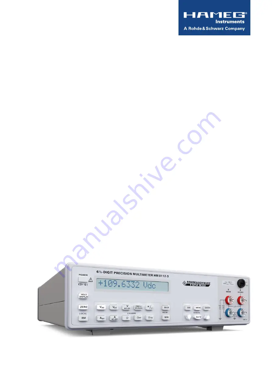
6 ½ - D i g i t P r e c i s i o n
m u l t i m e t e r
H m 8 1 1 2 - 3
Handbuch / manual
Deutsch / english
Page 1: ...6 D i g i t P r e c i s i o n m u l t i m e t e r H M 8 1 1 2 3 Handbuch Manual Deutsch English ...
Page 2: ... vorgeschrieben ist dürfen Signalleitungen Eingang Ausgang Signal Steuerung eine Länge von 3 Metern nicht erreichen und sich nicht außerhalb von Gebäuden befinden Alle Signalleitungen sind grundsätzlich als abgeschirmte Leitungen Koaxialkabel RG58 U zu verwenden Für eine korrekte Massever bindung muss Sorge getragen werden Bei Signalgeneratoren müssen doppelt abgeschirmte Koaxialkabel RG223 U RG21...
Page 3: ...erstandsmessung 15 5 2 Vierdraht Widerstandsmessung 15 5 3 Verlustleistung der Widerstände 15 6 Wechselspannungsmessung 16 6 1 Wechselspannungsmessung Grundlagen 16 6 2 Arithmetischer Mittelwert 16 6 3 Gleichrichtwert 16 6 4 Effektivwert 16 6 5 Formfaktor 17 6 6 Crestfaktor 17 6 7 Gleich und Wechselstrom 17 7 Temperaturmessung 17 7 1 Temperaturmessfühler 18 7 2 Platin Temperaturfühler PT100 18 7 3...
Page 4: ...ssung AC und DC AC R Mathematikfunktionen Grenzwerttest Minimum Maximum Mittelwert und Offset R Temperaturmessungen mit Temperaturfühlern PT100 PT1000 und mit Ni Thermoelementen K Typ bzw J Typ R Interner Datenlogger für bis zu 32 000 Messwerte R Offset Korrektur R Galvanisch getrennte USB RS 232 Dual Schnittstelle optional IEEE 488 GPIB R HM8112 3S HM8112 3 inkl Messstellenumschalter 8 1 Kanäle j...
Page 5: ...s bis 0 1 vom Messwert Crestfaktor 7 1 max 5 x Messbereich Eingangsschutz Sicherung FF 1A 250V Widerstand Messbereiche 100Ω 1kΩ 10kΩ 100kΩ 1MΩ 10MΩ Integrationszeit 0 1s 1 60s Messbereichsende 120 000 Digit 1 200 000 Digit Auflösung 1mΩ 100µΩ Genauigkeit errechnet aus rdg f s 1 Jahr 23 C 2 C Temp Koeffizient C Messbereich rdg f s 10 21 C 25 40 C 100Ω 0 005 0 0015 0 0008 0 0008 1kΩ 0 005 0 001 0 00...
Page 6: ...ert sollte vor dem Einschalten eine Zeit von mindestens 2 Stunden für die Akklimatisierung des Gerätes eingehalten werden 1 5 Sicherheitshinweise Dieses Gerät ist gemäß VDE 0411 Teil 1 Sicherheitsbestimmun gen für elektrische Mess Steuer Regel und Laborgeräte gebaut geprüft und hat das Werk in sicherheitstechnisch einwandfreiem Zustand verlassen Es entspricht damit auch den Bestimmungen der europä...
Page 7: ... w e i s e 7 Änderungen vorbehalten 1 6 cAt ii Die folgenden Erläuterungen beziehen sich lediglich auf die Benutzersicherheit Andere Gesichtspunkte wie z B die maxi mal zulässige Eingangsspannung sind den technischen Daten zu entnehmen und müssen ebenfalls beachtet werden Es ist auch möglich mit Hilfe geeigneter Wandler z B Stromzan gen welche mindestens die Anforderungen der Schutzklasse der durc...
Page 8: ...dukt oder Öffnen des Produkts ist dieses von der Versorgungsspannung zu trennen sonst be steht das Risiko eines elektrischen Schlages 1 10 Umschalten der Netzspannung Vor Inbetriebnahme des Gerätes prüfen Sie bitte ob die verfüg bare Netzspannung 115V oder 230V dem auf dem Netz span nungswahlschalter des Gerätes angegebenen Wert entspricht Ist dies nicht der Fall muss die Netzspannung umgeschaltet...
Page 9: ... HM8112 3S 30 Netzspannungswahlschalter 115 V bzw 230 V 29 28 30 9 Änderungen vorbehalten B e z e i c h n u n g d e r B e d i e n e l e m e n t e 2 Bezeichnung der Bedienelemente 1 DisPlAy 16 stelliges Display 2 PoWer Stand By EIN 3 HolD DisPlAy angezeigter Wert im Diplay speichern 4 Zero Nullabgleich der Messstrecke 5 rm locAl taste Fernbedienung über Interface ausschalten 6 VDc Gleichspannungs M...
Page 10: ...eigeumfang 0 0 0 0 0 0 0 0 0 0 0 0 0 0 bis bis 1 9 9 9 9 9 9 1 2 5 0 0 0 0 Messpunkte 2 0 0 0 0 0 0 Digit 1 2 5 0 0 0 1 Digit Messwert 1 1 0 V 1 0 V Anzeige 1 1 0 0 0 0 0 0 1 0 0 0 0 0 0 Messwert 2 1 2 5 0 0 0 0 V 1 2 5 0 0 0 0 V Anzeige 2 1 2 5 0 0 0 0 1 2 5 0 0 0 0 Messwert 3 1 2 6 0 0 0 0 V 1 2 6 0 0 0 0 V Anzeige 3 1 2 6 0 0 0 0 1 2 6 0 0 0 Dekadenwechsel Das DMM1 mit 2 000 000 Digit kann bis ...
Page 11: ...chen der idealen Umsetzungsfunktion und der wirklichen Um setzungsfunktion Der Linearitätsfehler gibt den größten Wert des Abstandes zwischen den beiden Funktionen an Abb 4 Wandelverfahren Nachfolgend werden das Single Slope Dual Slope und das Multi Slope Verfahren beschrieben Diese Sägezahn A D Umsetzer beruhen auf einem gemeinsamen Prinzip Die Umsetzung der Eingangsspannung in eine dazu proporti...
Page 12: ...den Integrator angeschlossene Referenzspannung Uref konstant ist dauert es unterschiedlich lange bis die Kapazität des Integrators entladen ist Es dauert länger die höhere Rampenspannung Ur1 zu entladen als die kleinere Rampenspannung Ur2 Aus dieser unterschiedlichen Entladezeit Δt2 t3 t2 und der konstanten Referenzspannung lässt sich die zu messende Eingangsspannung Ue bestimmen Vorteile DieGenau...
Page 13: ...ben Die Genauigkeitsangaben bei Multimetern bestehen aus ver schiedenen Größen Die Messabweichung wird angegeben als xx vom angezeigten Messwert xx vom Messbereich bei einer Temperatur xx C xx über einen Zeitraum von xx Stunden xx Tage xx Jahren Beispiel Messbereich 10 V 0 004 rdg 0 001 f s über 24h bei 23 1 C Der Temperaturkoeffizient TK gibt die Abweichung pro C über einen definierten Temperatur...
Page 14: ...ng Als Gleichtaktunterdrückung bezeichnet man die Fähigkeit ei nes Messgerätes nur das gewünschte Differenzsignal zwischen HI und LO Eingang anzuzeigen eine für beide Klemmen gleiche Spannung gegen Erde dagegen möglichst zu unterdrüc ken In einem idealen System würde kein Fehler entstehen In der Praxis wandeln Streukapazitäten Isolationswiderstände und ohmsche Unsymmetrien einen Teil der Gleichtak...
Page 15: ... einen Widerstand von ca 10 20 mΩ Bei einem zu messenden Widerstand von 100 Ω ergibt dies bereits einen Fehler von 0 04 Bei niedrigen Widerstandswerten insbesondere im 100 Ω Bereich macht sich der Zuleitungswiderstand also recht stark bemerkbar Für diese Bereiche ist daher eine Vierdraht Messung zu empfehlen 5 2 Vierdraht Widerstandsmessung Damit die durch Zuleitungswiderstände vorhandenen Mess pr...
Page 16: ...W Wechselspannungsmessung Das Multimeter HM8112 3 misst eine Wechselspannung als Echteffektivwert mit oder ohne Gleichanteil Eine für Wech selspannungsmessungen zu empfehlende Messanordnung besteht aus einem Zwei Leiter Kabel mit Abschirmung Die Abschirmung sollte mit Erde verbunden sein Etwas weniger Abschirmung erreicht man bei Verwendung eines einfachen Koaxialkabels Im 100 V und 600 V Bereich ...
Page 17: ...sich der Ef fektivwert des Signals Der Formfaktor eines Signals ermittelt sich nach folgender Formel Bei reinen sinusförmigen Wechselgrößen beträgt der Formfaktor π 2 2 1 11 6 6 Crestfaktor Der Crestfaktor auch Scheitelfaktor genannt beschreibt um welchen Faktor die Amplitude Spitzenwert eines Signals grö ßer ist als der Effektivwert Er ist wichtig bei der Messung von impulsförmigen Größen Bei rei...
Page 18: ...andes RL hervor Weil SENSE 24 die Messspan nung direkt am PT100 abgreift und der Eingangsverstärker des Messeingangs sehr hochohmig ist fließt ein vernachlässigbarer kleiner Strom in den SENSE Messleitungen Imess 0 Somit geht der Spannungsabfall über den SENSE Messleitungen hervorgerufen durch den Strom in den SENSE Leitungen nicht bzw vernachlässigbar in die Messung mit ein Auch hat eine Widersta...
Page 19: ... Austrittsarbeit zu verrichten und die Bindungskräfte im Metallgitter zu überwinden Berühren sich nun zwei Metalle deren Bindungskräfte unterschiedlich sind so treten aus dem Metall mit den kleineren Bindungskräften Elektronen aus und fließen zum Metall mit den größeren Bin dungskräften Schaltet man nun zwei solche Kontaktstellen zusammen und besitzen die beiden Enden des Thermoelementes ein unter...
Page 20: ...sen Als Basiszeit dient eine Sekunde Die erste auftretende negative Flanke triggert die Messung und startet den Zähler Eine Sekunde lang löst jede negative Flanke einen Zählimpuls aus Nach Ablauf der ersten Sekunde wartet die Messschaltung auf den nächsten Nulldurch gang des Signals Ab jetzt wird die Periodendauer des Signals bestimmt Es wird gemessen wie lange es bis zum folgenden Nulldurchgang d...
Page 21: ...usgelöst Der Zuleitungswiderstand der Messleitung Übergangs widerstände und Thermospannungen an den Übergängen verschiedener Metalle werden durch diese Offsetkorrektur bewusst eliminiert Die Kompensationswerte bleiben auch nach Ausschalten des HM8112 3 erhalten und müssen bei Bedarf neu ermittelt werden Ein Betätigen der ZERO Taste 4 in den Mess bereichen δPT für PT Messfühler oder δTH für Thermoe...
Page 22: ...ufgeru fen werden Die Anschlussbuchsen sind ebenfalls beleuchtet und zeigen die für die entsprechend gewählte Messfunktion zu benutzenden Anschlussbuchsen an Spannungsmessung 6 VDC Gleichspannungsmessung bis 600 V Es gibt keine Autorange Funktion für die Messbereiche 100 mV und 1 V 8 VAC Wechselspannungsmessung bis 600 V als True RMS ohne Gleichanteil Es wird mit einem Kondensator an den Messkreis...
Page 23: ...essstrom PT100 1 mA PT1000 100 µA Messspannung im Leerlauf ca 2 5 V Messzeit 100 ms bis 60 s Messpause nach Bereichs oder Funktionswechsel 100 ms Kalibrierung mit Widerstandsnormal PT100 1 kΩ Bereich PT1000 10 kΩ Bereich Linearisierung nach DIN IEC 751 14 δPT bei 2 Draht Temperaturmessung 2 Draht TemperaturmessungmitPlatintemperaturfühler PT100 oder PT1000 mit eingeschränkter Genauigkeit der Messu...
Page 24: ...ichsendwertes In den niedrigeren Bereich wird geschaltet wenn 10 des Bereichsendwertes unterschritten wird Ist bei automatischer Bereichswahl der angelegte Messwert zu groß erscheint die Meldung Overflow in der Anzeige Die Messbereichsautomatik AUTO ist mit Bedacht zu benutzen Wird an einer hochohmigen Quelle gemessen und liegt die Messspannung in der Ge gend 90 vom Messbereichendwert 1V kann bei ...
Page 25: ...U 2 Temp 16 8 4 2 Off default Messfühler auswählen PT100 PT100 Fe CuNi NiCr Ni MENU MENU 3 Sensor K J PT1000 PT100 Comp Referenzstelle für Thermo Element festlegen MENU MENU Comp Comp Ext Ice Comp PT Front Comp 23 C F default Status Information MENU MENU 4 Info Version Cal Date Ser Nr Version 070404 CalL Date 170504 Ser Nr 00007104 F C Auswahl Anzeige ENTER externes Eisbad PT Sensor oder23 C als R...
Page 26: ...audrate einstellen 7 Com MENU MENU Rs19200 Rs9600 Off Geräteabgleich 8 Cal Dieser Bereich ist passwort geschützt default Math Menu MENU MENU 5 Math Off Lo Limit Hi Limit Offset default Mess Stellenumschalter Kanalwahl MENU MENU 9 Mux empty Chanal 1 Chanal 8 ENTER Wert2 00002 ENTER Wertn 0000n ENTER MENU ESC Storage End mit oder Menü verlassen M e n ü s t r u k t u r Übersicht Menü Struktur Teil 2 ...
Page 27: ...er gewählt springt nach Übernahme des Wertes das HM8112 3 in die Messfunktion δTH 15 Ebenso springt nach Auswahl eines PT Fühlers das Gerät in die Messfunktion δPT 13 Der zuletzt eingestellte Fühlertyp bleibt auch nach Wegschal ten der Netzspannung im Gerät gespeichert K TYP Default nach Einschalten Netzspannung Thermoelement NiCr Ni J TYP Thermoelement Fe CuNi PT1000 Platinwiderstandssensor mit R...
Page 28: ... der Messsignale besitzt das HM8112 3 auf der Frontplatte vier Sicherheitsbuchsen Je nach eingestellter Messfunktion sind die aktiven Sicherheitsbuchsen beleuchtet Generell sind die Frontbuchsen über geeignete Sicherheitsstecker anzuschließen und die entspre chenden Sicherheitsbestimmungen zu beachten Beim Anlegen von berührungsgefährlichen Span nungen an die Eingangsbuchsen 24 und 26 müs sen alle...
Page 29: ... ist gefährlich und unzulässig Dadurch entstandene Schäden am Gerät fallen nicht unter die Garantieleistungen 10 10 Rückseite des HM8112 3 28 Kaltgeräteeinbaustecker mit Netzschalter Kaltgeräteeinbaustecker zur Aufnahme des Netzkabels mit Kaltgerätekupplung nach DIN 49457 29 Interface Auf der Rückseite des HM8112 3 befindet sich eine USB RS 232 Schnittstelle HO820 Mit dieser Schnittstelle kann das...
Page 30: ...1kOhm 10kOhm 100kOhm 1MOhm 10MOhm No Change 0 5 OHM 4WIRE 100Ohm 1kOhm 10kOhm 100kOhm 1MOhm 10MOhm No Change 8 FREQ PERIOD VAC FREQ PERIOD B Diodentest No Change C Durchgang 10 Ohm D Sensor RTD 2WIRE Pt100 Pt1000 E Sensor RTD 4WIRE Pt100 Pt1000 F Sensor TH J K 0 AUTO RANGE OFF ON UP DOWN 1 MEAS Time 10ms 50ms 100ms 500ms 1s 10s 60s UP DOWN 2 Filter CONT 2 4 8 16 0 4 Math OFF OFFSET HIGH LIMIT LOW ...
Page 31: ...sevonmindestens35mseingehaltenwerden Erst dann sollte der nächste Befehl eingegeben werden DieEingabeungültigerBefehlewirdmitderNachricht02D0für falscheNachrichtenlängeodernichtimplementierteBefehls Gruppen mit02D1fürGruppe1 mit02D2fürGruppe2undmit 02DE für Gruppe E beantwortet Dies hilft bei der Fehlersuche imSteuerprogramm DieseFehler Nachrichtenwerdensofort nach Auftreten ausgegeben Anmerkung z...
Page 32: ...ausgewählt wurde jeweils den nächsten Messwert vom ersten begin nend aus Mit diesem Befehl kann die Geschwindigkeit der Speicherausgabe kontrolliert werden Parameter 4 löscht den gesamten Messwertspeicher Parameter 5 bis 7 sind Gerätenachrichten 0195 signalisiert bei der Speicherausgabe das Ende eines Messwertspei chers 0196 meldet dass ein durch 01BX ausgewählter Messwertspeicher leer ist 0197 me...
Page 33: ...0111 7 0120 4 0140 0147 0148 0182 5 0190 0191 0198 01C1 01C2 Parameter 5 schaltet die kontinuierliche Statusfunktion ein Die Auto Statusfunktion wird falls aktiv ausgeschal tet Nach jedem Messergebnis wird die aktuelle Funktion und der aktuelle Bereich im Format 00XX ausgegeben Danach folgt die Angabe der Messzeit im Format 011X Eine durch eine Zustandsänderung des Gerätes ausgelöste Nachricht der...
Page 34: ...ed also such connections must not leave the premises All signal connections must be shielded e g coax such as RG58 U With signal generators double shielded cables are mandatory It is especially important to establish good ground connections 3 External influences In the vicinity of strong magnetic or and electric fields even a careful measuring set up may not be sufficient to guard against the intr...
Page 35: ... 2 Four wire resistance measurement 46 5 3 Power dissipation of the resistors 46 6 AC measurement 47 6 1 Basics of AC measurements 47 6 2 Arithmetic average value 47 6 3 Rectified value 47 6 4 Root mean square value 47 6 5 Form factor 47 7 Temperature measurement 48 7 1 Temperature sensors 48 6 6 Crest factor 48 6 7 DC and AC currents 48 7 2 Platinum temperature sensor PT100 49 7 3 Temperature mea...
Page 36: ...to a PC R True RMS Measurement AC and DC AC R Mathematic Functions Limit Testing Minimum Maximum Average and Offset R Temperature Measurements with Platinum PT100 PT1000 and Ni K and J types Sensors R Internal Data Logger for up to 32 000 Measurement Results R Offset Correction R Galvanically isolated USB RS 232 Dual Interface optional IEEE 488 GPIB R HM8112 3S HM8112 3 incl Scanner Card 8 1 Chann...
Page 37: ...g Crest factor 7 1 max 5 x range Input protection fuse FF 1A 250V Resistance Ranges 100 Ω 1kΩ 10kΩ 100kΩ 1MΩ 10MΩ Integration time 0 1s 1 60s Display ranges 120 000 digit 1 200 000 digit Resolution 1mΩ 100µΩ Accuracy Values given are in of reading of full scale 1 year 23 C 2 C Temp coefficient C Range rdg f s 10 21 C 25 40 C 100 Ω 0 005 0 0015 0 0008 0 0008 1kΩ 0 005 0 001 0 0008 0 0008 10kΩ 0 005...
Page 38: ...io nal standard IEC 61010 1 Please observe all warnings in this manual in order to preserve safety and guarantee operation without any danger to the operator According to safety class 1 requirements all parts of the housing and the chassis are con nected to the safety ground terminal of the power connector For safety reasons the instrument must only be operated from 3 terminal power connectors or ...
Page 39: ... personnel will be exposed to the risk of an electric shock I m p o r t a n t h i n t s 39 Subject to change without notice short fast and fast rise changes of voltage or current and may be periodic or non periodic The amplitude of transients increases with decreasing distance from their source CAT IV Measurements at the source of a low voltage supply e g at electricity meters CAT III Measurements...
Page 40: ...uring a test series 17 MIN min value during a test series 18 MENU Call of the menu acceptance of values entered 19 ESC Leaving the menu without acceptance of the values entered 20 down Switching to a higher range and scrolling down the menu 21 AUTO Activation Deactivation of the auto range function 22 ENTER Special function Parameter selection in the logger menu 23 up Switching to a lower range an...
Page 41: ... 0 0 0 0 0 0 0 0 0 to to 1 9 9 9 9 9 9 1 2 5 0 0 0 0 Measuring points 2 0 0 0 0 0 0 digit 1 2 5 0 0 0 1 digit Measuring result 1 1 0 V 1 0 V Display 1 1 0 0 0 0 0 0 1 0 0 0 0 0 0 Measuring result 2 1 2 5 0 0 0 0 V 1 2 5 0 0 0 0 V Display 2 1 2 5 0 0 0 0 1 2 5 0 0 0 0 Measuring result 3 1 2 6 0 0 0 0 V 1 2 6 0 0 0 0 V Display 3 1 2 6 0 0 0 0 1 2 6 0 0 0 Change of decades DMM no 1 with 2 000 000 dig...
Page 42: ... an offset error in the a d conversion Fig 1 Slope error amplification factor error of the A D converter The input amplifier s amplification factor is temperature dependent or the amplification factor was maladjusted Hence the slope of the function differs from the ideal value Fig 2 Differential nonlinearity of the A D converter The quantizing steps of the a d converter are unequal in size and dif...
Page 43: ... and a lower ramp voltage see Vr2 As the reference voltage which is connected to the integrator at t2 is constant the downward slope is constant hence the time for disharging the integration capacitor differs It takes more time to discharge the higer ramp voltage Vr1 than for discharging the smaller ramp voltage Vr2 The input voltage Vin can thus be determined from the respective discharge time sp...
Page 44: ...rator Output Zero Δt4 The charge caused by the integrator overshoot will be discharged 3 8 Accuracy specifications The accuracy specifications of multimeters consist of diverse numbers and units The measurement deviation is specified as xx of measurement xx of range at a temperature of xx C xx this will apply for a time span of xx hours xx days xx years Example Measuring range 10 V 0 004 of rdg 0 ...
Page 45: ...ment to only display the desired difference signal between the HI and LO input terminals while suppressing any signals referenced to to ground common to both input terminals as far as possible In an ideal system there would be no error in practice stray capacitances isolation resistances and ohmic unsymmetries convert part the common mode signal to series mode 4 4 Thermal voltages One of the most ...
Page 46: ...ance thus beco mes remarkable In these ranges 4 wire measurements are recommended 5 2 Four wire resistance measurement In order to prevent the measuring problems caused by the cable resistances the 4 wire circuit is used for all small resistors In a 4 wire measurement circuit also a current from a precision current source flows through the resistor R The voltage drop across R is taken off directly...
Page 47: ...Iû sinωtI dt û 0 637û T 0 π _ 1 T x t 2 x t 2 dt T 0 1 T xeff x t 2 dt T 0 1 T û U û sinωt 2 dt 0 707û T 0 2 xrms 3 Messgrundlagen Verwendete Abkürzungen und Zeichen W Wirkleistung P VA Scheinleistung S var Blindleistung Q u t Spannung Momentanwert u t Spannung quadratischer Mittelwert IÛI Spannung Gleichrichtwert Ueff Spannung Effektivwert û Spannung Spitzenwert Ieff Strom Effektivwert î Strom Sp...
Page 48: ...stance of conductors and cables The measurement error in follows from 100 x VB Error VS DMM Rs V Vs R RL Crest Form factor factor C F 2 1 11 2 1 11 2 1 57 3 1 15 π 2 Form factors π 2 2 π 2 2 2 3 7 Temperature measurement In the international SI system of units the Kelvin K was defi ned as the basic unit for temperature measurements Degree Centigrade C is a lawful unit derived from the SI units and...
Page 49: ...Cr Ni thermocouple K Type The application range of a NiCr Ni thermocouple of the K type is from 270 C bis 1 300 C As the name implies the themocouple delivers a voltage This temperature dependent voltage is generated at the contact junction of two dissimilar metals It is called contact or thermal voltage Due to the steady thermal movement of the electrons in the metal s lattice some electrons at t...
Page 50: ...to the measu rement system by socalled extension wires which are made of the same materials that form junction 1 As a rule the signal has to be sent over quite a distance therefore the extension wires have to be contacted to regular copper wires These contacts form a pair of junctions which constitute junc tion 2 In order to guarantee a decent accuracy those contact terminals are mounted on a soca...
Page 51: ...until the next zero point occurs The measurement result determines the frequency of the signal and the period will be calculated from the frequency This combined measurement of the number of zero points and of the period of a signal allows the measurement of very small as well as very high frequencies within a reasonable time Applying of a DC voltage results in a frequency displayed of 0 Hz As the...
Page 52: ... sending a command via interface to the HM8112 3 the instru ment is set to the remote mode Remote control is switched off by pressing button LOCAL The instrument returns to manual mode and can be operated from the front panel 10 2 Buttons for the various measurement functions If the measurement function is changed the HM8112 3 assumes the sampling rate selected unless a sampling rate between 10s a...
Page 53: ... 600 V true RMS wit hout the DC component 100mV range is not possible In AC a capacitor is inserted The input impedance of the HM8112 3 is Ri 10 MΩ 10 VAC DC Alternating voltage measurement up to 600 V true RMS with DC component Direct coupling of the circuit to the instrument and using of the same high precision input divider like VDC The input impedance of the HM8112 3 is 10 GΩ in 100 mV range 1...
Page 54: ...y Dimension C or F Linearisation according to EN60584 V A SENSE SOURCE LO HI max 250Vrms max 850 Vpk max 850 Vpk Ω ϑ FUSE 1A F250V CAT II max INPUT 600Vrms 1Arms Power input Source 10 3 Continuity test 14 Continuity and diode test Continuity test Activating of the loudspeaker for measured values between 0 Ω short circuit and approx 10 Ω Diode test Test voltage approx 2 5 V Test current 1 mA consta...
Page 55: ...switch on a value of 100 ms will be preset Removal of the line voltage will not save a selected value If the measurement function is changed the HM8112 3 assumes the default sampling rate unless a sampling rate between 10 s and 60 s is chosen Then changing the measuring function sets the sampling rate automatically to 1 s Example The sampling rate for VDC is set to 60 s Then the func tion ADC is s...
Page 56: ...t Choice temperature sensor PT100 PT100 Fe CuNi NiCr Ni MENU MENU 3 Sensor K J PT1000 PT100 Comp Fixing the reference for the thermocouple MENU MENU Comp Comp Ext Ice Comp PT Front Comp 23 C F default General information MENU MENU 4 Info Version Cal Date Ser Nr Version 070404 CalL Date 170504 Ser Nr 00007104 F C Selection Display ENTER Specification of an external ice bath PT sensor or 23 C as ref...
Page 57: ... bath would be necessary for each thermocouple To overcome this the ambient temperature or even a source with a constant temperature is taken as the refe rence e g ice bath heated reference If PT Front is seleced by pressing MENU 18 the function δPT will be activated Now 2 or 4 wire measurement can be chosen Then the reference temperature is measured with a platinum sensor and assumed by confirmat...
Page 58: ...Depending on the measu rement function chosen the active terminals will be illuminated The terminals on the front panel are safety con nec tors and the regulations have to be observed If connecting dangerous voltages to the input termi nals 24 and 26 all relevant safety regulations are to be observed DC voltage must be floating AC voltage must be floating by use of a safety isola ting transformer ...
Page 59: ...cle with power switch Power receptacle for connecting the line cord with according to DIN49457 29 Interface The USB RS 232 interface is located at the rear panel of the HM8112 3 The interface of HM8112 3 can receive data com mands from an external device PC or send data measurement values and parameters The following option is available HO880 IEEE 488 GPIB In order to avoid the warranty seal broke...
Page 60: ...and category with 02D1 for group 1 with 02D2 for group 2 and with 02DE for group E This helps debugging the controller program The error message is transmitted immediately after occurrence Notes concerning some commands 0000 0004 Measurement of DC voltage ranges 100 mV to 600 V 0010 0014 True RMS with DC 0016 0019 True RMS without DC 02C3 02C5 This message is sent after a change of function or ran...
Page 61: ...d in a ring buffer which holds the last 15 results Un less the results are fetched by the commands 01A2 or 01A3 the oldest result will be overwritten In case the autostatus function is selected the transmission of status information will be inhibited this information will be lost see commands 02C4 and 02C5 Without a command from the controlling unit the instrument will not transmit any information...
Page 62: ...smitted in place of the measurement time synchronously with the next result In case there will be more than one group 1 information caused by a keyboard operation or by the instrument s control program e g result memory full auto range within the same measurement cyc le those informations will overwrite each other Only the last information will be transmitted with the next result Range or function...
Page 63: ...m 10kOhm 100kOhm 1MOhm 10MOhm No Change 0 5 OHM 4WIRE 100Ohm 1kOhm 10kOhm 100kOhm 1MOhm 10MOhm No Change 8 FREQ PERIOD VAC FREQ PERIOD B Diode test No Change C Continuity 10 hm O D Sensor RTD 2WIRE Pt100 Pt1000 E Sensor RTD 4WIRE Pt100 Pt1000 F Sensor TH J K 0 AUTO RANGE OFF ON UP DOWN 1 MEAS Time 10ms 50ms 100ms 500ms 1s 10s 60s UP DOWN 2 Filter CONT 2 4 8 16 0 4 Math OFF OFFSET HIGH LIMIT LOW LI...
Page 64: ... Data without tolerance limits is not binding R S is a registered trademark of Rohde Schwarz GmbH Co KG Trade names are trademarks of the owners Rohde Schwarz GmbH Co KG www rohde schwarz com Contact Customer Support www customersupport rohde schwarz com Service www service rohde schwarz com Additional Questions ROHDE SCHWARZ GmbH Co KG Mühldorfstraße 15 D 81671 München Phone 49 89 41 29 0 Fax 49 ...