background image


Page 12 of 25  

The Constant Fraction Discriminators CFD8c, CFD7x, CFD4c, CFD1c and CFD1x (11.0.1701.1)  


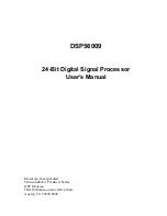
Figure 3.9b: Signal traces (as in Figure 3.8b left) but with too long (left picture) and too short delay cable (right) 


Figure 3.10b: Signal traces (as in Figure 3.8b left) with a too short delay cable (left picture). This can fairly be 

compensated by increasing the CFD fraction from 0.35 to 0.6 (right picture) 

3b.3.3


CFD fraction 

Optimal choice of the 

CFD fraction

  ratio is as important as the appropriate selection of the 

CFD delay

  and is linked to it 

according to the above guide lines. Ideally, these two parameter settings will result in a bipolar signal in such a way that the 

zero-crossing happens with the maximum possible slope. Although this depends on the exact shape of the signal a 

CFD fraction

 ratio between 0.3 and 0.45 will give optimal results for near-Gaussian shaped input signals (only the rising edge is 

relevant). 

RoentDek


delivers the CFD with a standard 

CFD fraction

 setting of about 0.35. The 

CFD fraction

 can be varied 

between 0.15 and 1 via a potentiometer.  


In order to observe and quantify the 

CFD fraction

 ratio on the oscilloscope one can use a very long delay cable and estimate the 

relative pulse heights when the signal portions appear distinct as in Figure 3.9b left (comparing positive and negative signal 

height). 


Under certain experimental conditions it may be beneficial choosing a higher or lower 

CFD fraction

 ratio than the default value. 

CFD fractions

 smaller than 0.3 should generally only be set for high signal-to-noise ratio. Then a  low 

CFD fraction

 can be of 

advantage in case of non-linear amplification of the input signals (e.g. presence of saturation effects in the amplifier before the 

CFD) or in case of varying relative signal width (FWHM) as function of pulse height. Low fraction values may also improve 

the temporal resolution for very short signals (< 3 ns FWHM). Furthermore, choosing a very short delay cable (i.e. 0.5 ns) in 

combination with a high Walk level can force the CFD into the operation mode of a leading edge discriminator. 

Summary of Contents for CFD1c

Page 1: ...Dek Handels GmbH Supersonic Gas Jets Detection Techniques Data Acquisition Systems Multifragment Imaging Systems The RoentDek Constant Fraction Discriminators CFD8c CFD7x CFD4c CFD1c and CFD1x 11 0 17...

Page 2: ...Kernphysik Max von Laue Str 1 D 60438 Frankfurt am Main Germany Web Site www roentdek com WEEE DE48573152 Product names used in this publication are for identification purposes only and may be tradema...

Page 3: ...3 CFD fraction 12 3b 3 4 Walk level 13 3b 3 5 Output signal width 14 3B 4 THE VETO OPTION 14 3b 4 1 Accessing the jumpers in CFD1c CFD1x 16 3b 4 2 Accessing the jumpers in CFD8c and CFD7x 16 3b 4 3 A...

Page 4: ...Page 4 of 25 The Constant Fraction Discriminators CFD8c CFD7x CFD4c CFD1c and CFD1x 11 0 1701 1...

Page 5: ...Constant Fraction DiscriminatorsCFD8b CFD4b and CFD1b 11 0 1701 1 Page 5 of 25...

Page 6: ...odules containing such boards please review first Chapters 3b 1 to 3b 3 and then refer to Chapter 3b 7 to learn about the difference between the standard CFD and the RoentDek bCFD settings 3b 1 Genera...

Page 7: ...weight 0 8 kg with an external 12 V DC mains adapter for use with 100 250 V AC sockets The power consumption is max 0 5 A at 12 V DC 6 W or max 0 7 A at 12 V DC 10 W for the CFD1x The CFD4c has the s...

Page 8: ...fraction is determined by the choice of fix resistors or a potentiometer as in case of the RoentDek CFDs While one of the signals is inverted later on the other experiences a certain delay CFD delay...

Page 9: ...he signals have to be verified on an oscilloscope The CFD Fraction can be adjusted by another potentiometer labelled Fr on the front panel CFD4b CFD1b side panel CFD8b top lid see Figure 3 6b Figure 3...

Page 10: ...s damped by a factor of 10 For achieving the ideal settings it is first of all important to note that the CFD operates best in all respects and yields the optimal temporal resolution if the input sign...

Page 11: ...delay D of 5 5 ns Note that the RoentDek CFDs will not operate without connecting an external delay cable bridge If the pulse rise time RT is defined as the time from reaching 10 to 90 of the signal m...

Page 12: ...livers the CFD with a standard CFD fraction setting of about 0 35 The CFD fraction can be varied between 0 15 and 1 via a potentiometer In order to observe and quantify the CFD fraction ratio on the o...

Page 13: ...during the bipolar signal s crossover while fluctuating almost equally between high and low states before and long after the signal due to electronic noise on the line not visible in the pictures If...

Page 14: ...idth bridges of the internal circuit see Figure 3 5b With the jumper in place the maximum width is increased to 2000 ns Please contact RoentDek if you are in need of the optional jumpers Obviously a s...

Page 15: ...15b Trace of the input signal to the Veto socket upper trace and signal traces of CFD timing signals lower trace integrated over many events for Veto left and Gating mode right In order to work reliab...

Page 16: ...he front panel 3b 4 2 Accessing the jumpers in CFD8c and CFD7x I Disconnect the mains power supply II On the rear panel remove all five screws red circles Please note that different types and sizes of...

Page 17: ...ear front panel and fix them with all screws and hex bolts 3b 4 3 Accessing the jumpers in CFD4c I Remove all six screws from the right side panel marked in red see Figure 3 20b Figure 3 20b Side pane...

Page 18: ...oscope see Figure 3 21b If a CFD is used for operating a RoentDek delay line detector or similar device these pre trigger events result in a distinct structure in the time sum spectrum see Figure 3 21...

Page 19: ...neighbours 3b 6 The CFDx pulse height determination option The CFDx function is an add on circuit that allows measuring the signal s pulse height The pulse height information is coded as a time delay...

Page 20: ...er trace ramp monitor output the Ramp switch is turned off here Signals are triggered on the CFD timing output signal trace not shown Left and right pictures were obtained with two different cable len...

Page 21: ...Dx signal This is indicated in Figure 3 26b The ramp slope is about 1 V per 12 ns giving an almost linear correspondence between pulse height and time delay with a typically 10 to 20 ns offset for pul...

Page 22: ...iming signal with a RoentDek TDC8HP The same spectrum could be recorded by plotting the time difference between trailing and leading transitions of the CFDx output It is advisable to mark the pulse he...

Page 23: ...se heights will not be registered Please contact RoentDek for advice unless you have received a properly matched system with bFAMP for a certain delay line read out anode Timing signals off the MCP co...

Page 24: ...3 12B SIGNAL TRACES AS IN FIGURE 3 8B LEFT WITH THE WALK LEVEL SET TO THE BASELINE OF THE INPUT SIGNALS LEFT PICTURE AND SLIGHTLY TOWARDS THE POSITIVE SIDE WHERE THE NOISE TRIGGERS BEGIN TO VANISH RIG...

Page 25: ...DTH POTENTIOMETER SETTING LOWER TRACE RAMP MONITOR ALL TRACES TRIGGERED ON THE STOP SIGNAL THE STOP SIGNAL SHOULD BE USED IF THERE IS A SPARE TDC CHANNEL AVAILABLE 21 FIGURE 3 27B AS FIGURE 3 25B RIGH...

Reviews: