`
22.
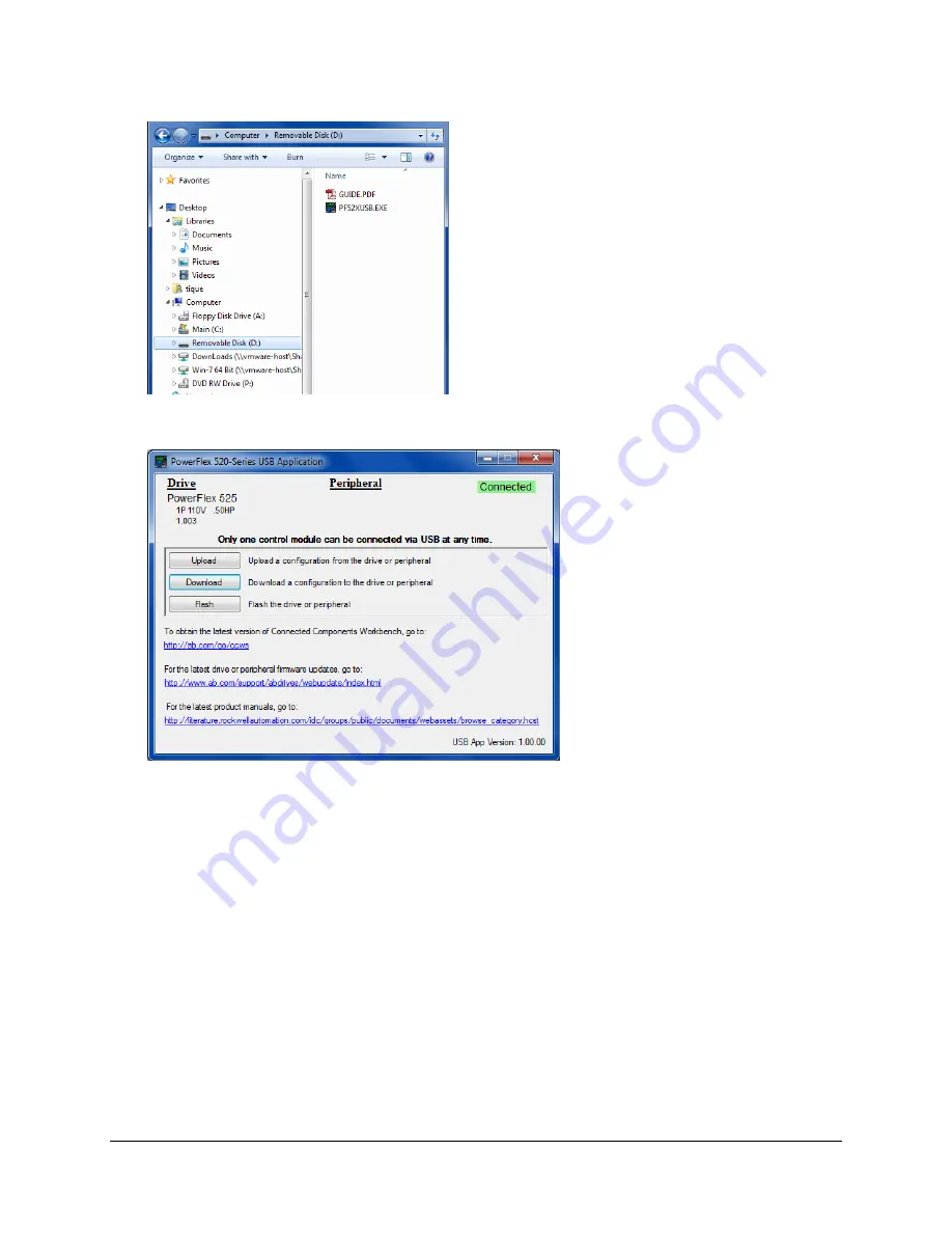
Open the Explorer Folder window and click on the “Removable Drive”. Then double mouse click on the PF52xUSB.exe file.
23.
Take what you have learned earlier from the uploading procedure and by selecting “Download” move the PF525_Drive.PF5
back to the drive.
Note: Refer back to Execise 2. This will verify that you have understood the purpose of the PF525_Drive.PF5 file which is
just a container used to get the drive information in and out of the drive when Main power is not applied to the drive.
Remember you do not need to use this file if you plan to connect to the drive when it has power applied to it.
In the next exercise we will validate the drive parameters by connecting or going on line with the drive using the CCW
Software.
24.
Disconnect the USB cable from the drive.
25.
Reconnect Control Module with the Power Module. Do Not Force the connection between the surfaces are properly mated
they push together fairly easily. Please ask for assistance if you are having any trouble (that is our nice way of saying
please don’t break drive) with the assembly.
26.
With the drive properly assembled apply power to the drive.
27.
Connect the Ethernet (E-Net) Patch cord to the Switch located on the PLC demo.
28.
Verify the Laptop PC has its E-net Patch cord connected to the Switch on the PLC demo
29.
Verify the PLC E-net Port is connected to the Switch on the PLC Demo.
Page
22
of
64


