


Publication 700-AT001A-EN-E June 2002
Considerations When Designing SSR Control Systems
2-21
external heat sinks when load current exceeds 3…6 A. When using
either of these SSRs, select an ideal combination of the SSR and heat
sink according to the load current.
The following combinations of SSR and heat sinks are ideal:
A standard, non-Allen-Bradley heat sink can be used, on condition
that the thermal resistance of the heat sink is lower than that of
Allen-Bradley’s heat sink.
For example, cat. no. 700-S20 has a thermal resistance of 1.63
°
C/W.
If the thermal resistance of the standard heat sink is lower than this
value (i.e., 1.5
°
C/W, for example), the standard heat sink can be used
for Bulletin 700-SH_.
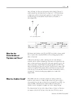
Thermal resistance indicates a temperature rise per unit (W). Heat
radiation efficency increases with a decrease in thermal resistance.
Calculating Heat Sink Area
An SSR that uses an external heat sink can be directly mounted to
control panels under the following conditions.
If the heat sink is made of steel used for standard panels, do not apply
a current equal or greater to 10 A, because the heat conductivity of
steel is less than that of aluminum. Heat conductivity (in units of W •
m • °C) varies with the material as described below.
6WHHO«
$OXPLQXP«
The use of an aluminum-made heat sink is recommended if the SSR is
directly mounted to control panels. Refer to the installation guide of
the SSR for the required heat sink area.
SSR Cat. No.
Heat Sink Cat. No.
700-SH40_
700-S30
700-SE10_
700-S10