Publication 700-AT001A-EN-E June 2002
Q & A
4-3
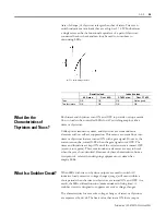
(rate of change) of thyristors is larger than that of triacs. Triacs can
switch inductive motor loads that are as high as 3.7 kW. Furthermore,
a single triac can be the functional equivalent of a pair of thyristors
connected back-to-back and can thus be used to contribute to
downsizing SSRs.
What Are the
Characteristics of
Thyristors and Triacs?
Both triacs and thyristors turn ON and OFF to provide or stop current
flow to loads to be controlled. SSRs for AC switching employ either
triacs or thyristors.
Unlike power transistors, triacs, and thyristors are semiconductor
elements with no self-arc suppression. This means a current flows into
triacs or thyristors that are turned ON with a gate signal. However, the
current cannot be, turned OFF when the gate signal turns OFF. The
triacs and thyristors are kept ON until the
output
current is turned OFF
(at zero cross point). These semiconductor elements are easy to break
when they are short-circuited. Be aware of these characteristics from a
viewpoint of safety when designing equipment or systems that
employ SSRs.
What Is a Snubber Circuit?
When SSRs with triac or thyristor outputs are used to switch AC
inductive loads, excessive voltage changes (surge) will occur within a
short period when the triacs or thyristors are turned ON and OFF. As a
result, the SSRs will malfunction (make mistakes in firing time). A
snubber circuit is designed to suppress excessive voltage changes.
The characteristics for excessive voltage changes of triacs or thyristors
are expressed by dv/dt. The limit value that turns ON these output
5HVLVWLYHORDG
,QGXFWLYHORDG
$PD[
2YHU$
N:PD[
2YHUN:
7ULDF
2.
2.
2.
1RWDVJRRG
7ZRWK\ULVWRUV
2.
2.
2.
2.
∆
9
∇
7 GYGW9ROWDJHULVHUDWH


