Rockwell Automation Publication 2198-RM005A-EN-P - October 2020
21
Replacement Considerations Chapter 1
Kinetix 350 Motor Brake Output
The two digital outputs (IOD-43 and IOD-44) have fixed pin assignments for
motor brake function.
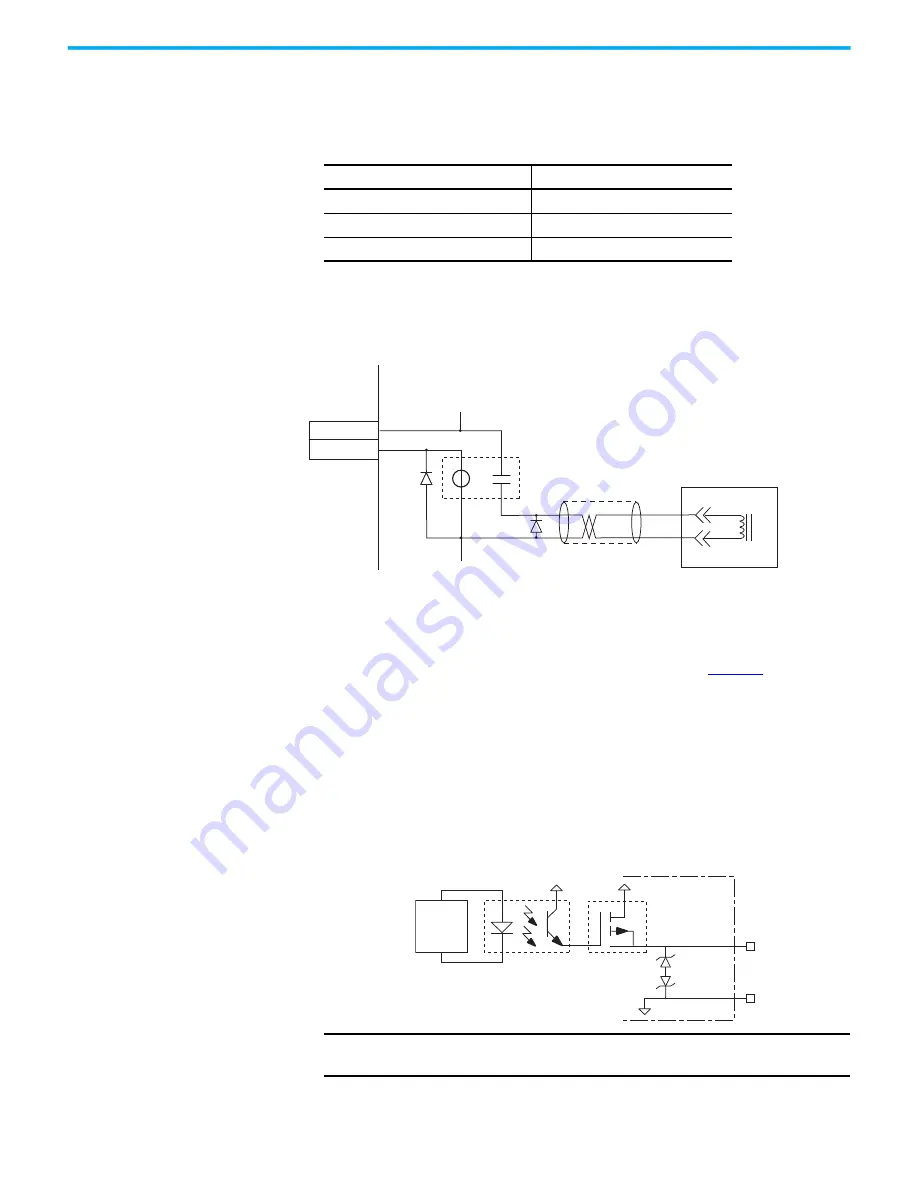
The following schematic shows a typical wiring configuration for the motor
brake circuit with a Kinetix 350 drive.
Figure 5 - Brake Wiring Schematic
Kinetix 5300 Motor Brake Output
Two connections (MBRK+ and MBRK-) are required for the motor brake
output. Connections are rated for 2.25 A @ +24V (refer to
When replacing a Kinetix 350 with a Kinetix 5300, do not wire a customer
supplied power supply to the motor brake circuit of the Kinetix 5300 drive.
Instead, either wire the motor brake circuit directly to the motor brake, or use
the 24V supplied by the Kinetix 5300 motor brake connector to drive an
interposing relay. In many cases the external relay circuit can be removed,
because the Kinetix 5300 can drive 2.25 A motor brakes directly, which is
sufficient for most applications.
Figure 6 - Motor Brake Circuit
Attribute
Value
Circuit type
Optically isolated open collector/emitter
Voltage, max
30V DC
Current, max
100 mA
BR+
BR-
7
9
White
Black
CR1
MTR
MTR_BRAKE -
24V DC
24V DC COM
43
44
Motor Brake
Kinetix 350 Drive
ISP772
MBRK+ (BC-1)
MBRK– (BC-2)
24V PWR
24V COM
INT PWR
Kinetix 5300
Servo Drive
Control
Board
Inductive
Energy
Clamp
IMPORTANT
Motor parking-brake switching frequency must not exceed
15 cycles/min.


