background image

F

-

H Series


Adjustments and Maintenance


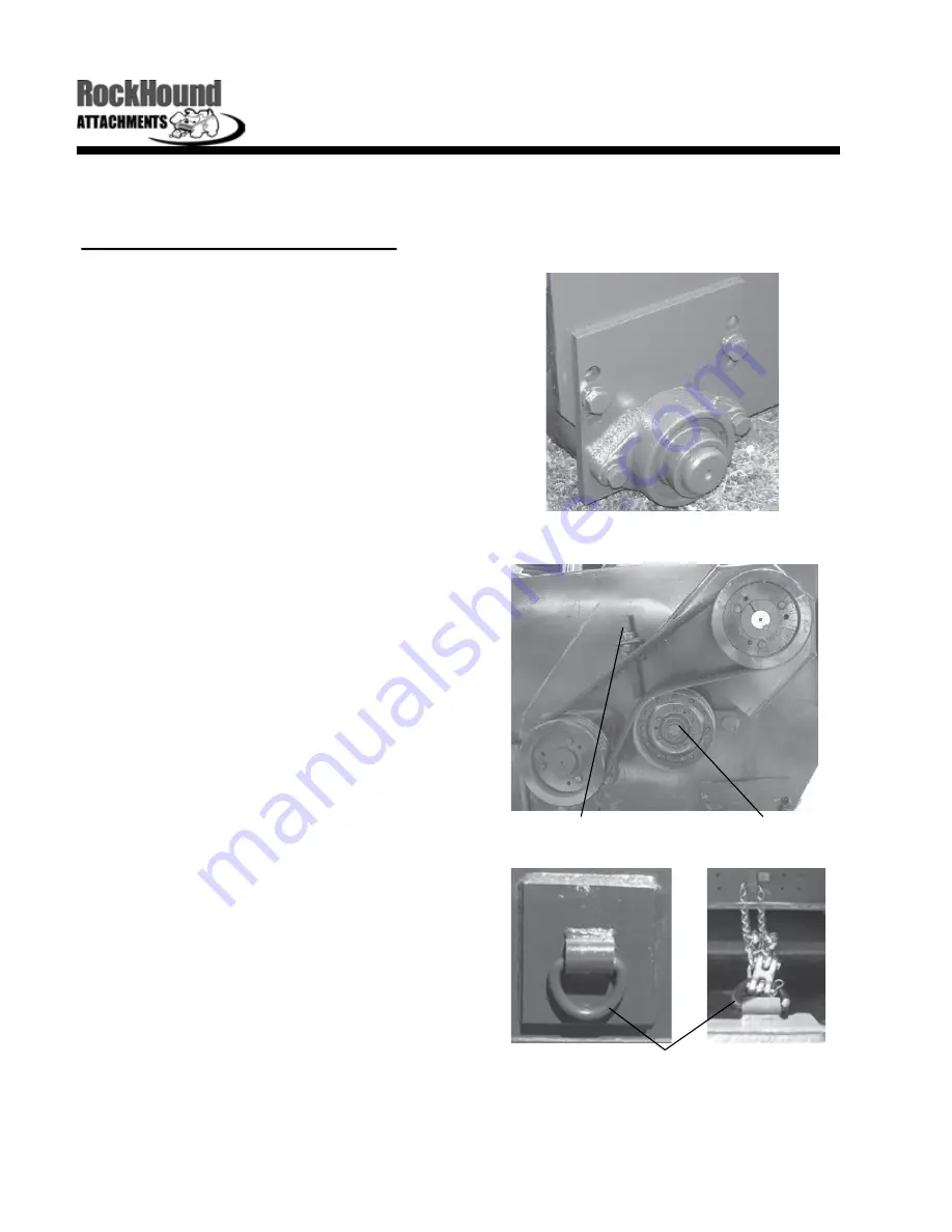
Cutting Height and Belt Adjustment


1.


The  cutting  height  of  the  shredder  can  be 

adjusted  from 

0

-

6”.   

Adjustment  is  done  by 

adjusting  the  height  of  the  gauge  roller  on 

the side of the shredder that is closest to the 

operating  vehicle  and  then  adjusting  the  tilt 

on the operating vehicle so that the desired 

cutting height is achieved.


2.


Adjusting the height of the back gauge roller 

is  done  by  removing  the  two  bolts  on  the 

height  adjusting  plate  on  both  sides  of  the 

shredder and sliding the plate up or down to 

achieve  the  desired  height.    The  weight  of 

the shredder should be on the gauge roller, 

not on the front of the shredder.


3.


Belt  adjustment  is  done  by  tightening  the 

idler  adjusting  rod  which  pulls  the  idler  pul-

ley into the belts.  On a new machine, after 

1

-

2  hours  of  operation,  tighten  the  drive 

belts so there is only 

1/4” 

to 

3/8” 

give with 8 

pounds of force.


Gauge Roller Adjustment


Idler Adjusting Rod


Height Adjustment Ring


4.


If  your  BrushHound  has  the  optional  skid 

shoes,  replacing  or  installing  these  is  done 

by  removing  the  two  bolts  holding  them  in 

place and simply reinstalling new ones using 

the two bolt holes that the old ones were re-

moved from.


5.


Adjustment  of  the  height  limiter  is  done  by 

increasing  or  reducing  the  amount  of  slack 

in  the  chain  going  from  the  ring  on  the 

shredder  to  the  operating  vehicle.    More 

slack  will  allow  the  machine  to  be  raised 

higher and less slack will keep it lower to the 

ground.


Idler Pulley


www.rockhound.com      10


Summary of Contents for BrushHound 60F-H

Page 1: ......

Page 2: ......

Page 3: ...grease fittings and proper daily maintenance routine Buyer is shown correct operation procedures including correct height of attachment All bolts checked for tightness Front demolition door option wa...

Page 4: ......

Page 5: ...unning Your Attachment Adjustments and Maintenance Lubrication Cutting Height and Belt Adjustment Replacing Knives Cleaning Your Shredder Hydraulic Plumbing Diagram Transport Removal and Storage Frequ...

Page 6: ...reviously manufactured If at any time you require additional information consult your authorized dealer or the customer service department ATTENTION The safety of the operator was one of the primary c...

Page 7: ...Shredder to be free from defect in material and workmanship for a period of six months dating from delivery to the origi nal user The obligation under this warranty statutory or otherwise is limited t...

Page 8: ...tor to lose awareness of what he she is doing It is recommended that scheduled work breaks be taken to avoid this Keep hands and loose clothing away from any power driven parts Avoid contact with hot...

Page 9: ...e attachment Never allow children or other persons to ride on the attachment Drive at a speed you can safely operate the vehicle and attachment Normal ground speed ranges from 0 5 miles per hour Use s...

Page 10: ...ction and exercise care when handling blades Also be alert to worn or damaged surfaces that could have sharp edges Disengage hydraulics and shut off engine allowing all movement to stop before leaving...

Page 11: ...kid steer and tilt it forward so that it can scoop up under the mounting plate on the shredder 3 Slowly move the skid steer forward until it taps against the shredder 4 Raise the front mount up on the...

Page 12: ...gage auxiliary flow hydraulics at a high engine speed 2 With low RPM turn on the auxiliary flow hydraulics 3 Slowly bring up the RPM to maximum flow efficiency IMPORTANT Should excess vibrations occur...

Page 13: ...nal skid shoes make sure they are not running on the ground They are made only to collide with small hills mounds or other uneven surfac es and are not made to run on the ground 6 Cutter drum rotation...

Page 14: ...each end of the shredder to prevent accidental lowering of the machine 3 Remove the ignition key from the operating vehicle and allow all movements to stop be fore beginning work Lubrication 1 GREASE...

Page 15: ...of the shredder 3 Belt adjustment is done by tightening the idler adjusting rod which pulls the idler pul ley into the belts On a new machine after 1 2 hours of operation tighten the drive belts so th...

Page 16: ...b All you need is a 3 16 punch a hammer and access to the knives on the cutter drum Once the shred der is tilted to where the knives are exposed simply take your punch and hammer it against the roll p...

Page 17: ...re that grease is not allowed to get into the belt areas 2 Clean clippings from hydraulic hose areas mounting areas or any other areas that may be susceptible to excessive heat 3 Clean the inside of t...

Page 18: ...epresents the hydraulic plumbing system for the 72F H and 84F H attachments To reverse cutter drum rotation reverse the hoses at the motor On quick couplers the male end is usually the pressure in On...

Page 19: ...ning work To transport disengage auxiliary hydraulics and lower the machine to a reasonable ride height Removal 1 Lower the shredder all the way onto the ground 2 Unlock the locking devices on the ope...

Page 20: ...edy the problem replace the belt Con sider having an extra belt on hand as well Q Do I need to fill the hydraulic motor with fluid before I use the mower A No this does not apply to the F H series mac...

Page 21: ...to reverse cutter drum rotation it is their responsibility to make sure that it is safe However RockHound Attachments recom mends running the cutter drum in the reverse rotation opposite tire rotatio...

Page 22: ...alog F H Specifications Model Cutting Width Appx HP Weight 60F H 72F H 60 72 84 72 84 96 1525 lbs 1750 lbs 1925 lbs F H Series BrushHound Overall Width Knives 32 40 48 Gauge Roller Dia 2 2 2 17 www ro...

Page 23: ...Assembly Description Model Part Quantity 1 2 3 4 5 Knife Bolt Knife Blade Spacer Castle Nut Roll Pin All All All All All CD 40EX 30 CD 2500 CD 40EX 32 CD 40EX 34 CD 40EX 35 A R A R A R A R A R 2 4 5 3...

Page 24: ...iple Seal Back Roller Adjusting Plate Left Back Roller Adjusting Plate Right End Plate Slot Filler Cutter Drum Bearing Cutter Drum Bearing Retainer Cap Model 60F H 72F H 84F H All All All All All All...

Page 25: ...om 2 7 16 ID Idler Pulley Idler Arm Idler Arm Adjusting Rod Drive Belt Single Drive Belt Banded Drive Belt Cover Model All All All All All All All All All All Part P 1480 P 1480 TL 1565 TL 1570 IP 164...

Page 26: ...ad Adapter Hydraulic Motor Model All All All All All All All All All Part HY 2450 HY 2520 HY 2545 HY 2535 HY 2530 HY 2560 HY 2570 HY 2610 HY 2900 Qty 1 A R A R 1 1 2 2 1 1 Year 2005 2005 2005 2005 200...

Page 27: ......

Page 28: ...e Flatface Coupler 3 4 M ORB x 3 4 M JIC 90 Adapter 3 4 M ORB x 3 4 M JIC Adapter 1 M ORB x 3 4 M JIC 90 Adapter 30 Hydraulic Hose Assembly 72 Hydraulic Hose Assembly Case Drain Hose Assembly Stand 3...

Reviews: