


page16
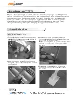
Get your model ready to fly
2.
Make sure all servo arms are fully vertical. If not, adjust the servo arm by using the trim
function on your radio.
Note
: For computerized transmitters, use the servo/channel
sub-trim feature to make each servo arm fully vertical.
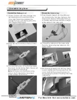
3.
The standard hole settings for linkage connections are shown by the black arrows in the
the diagram below. You can move the linkage to different hole positions to increase
control surface travel and increase the aerobatics of the airplane.
4.
Align aileron and flap with the wing root by turning the clevis clockwise and
counterclockwise on the linkage, carefully open the clevis fork and put the clevis pin in
the desired hole of the control horn.
Note
: Please secure the clevis with provided piece of tube after the alignment of the
surface is completed.
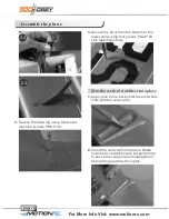
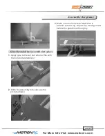
5.
Adjust the control connector on the servo arm to align the elevator and the rudder well.
Note:
Make sure the tail wheel align with the fuselage centerline while adjust the rudder.
4.1
4.2
5.1
5.2
For More Info Vist: www.motionrc.com
Summary of Contents for Beechcraft
Page 1: ...Email info motionrc com Http www motionrc com...
Page 2: ...Beechcraft...