Section ELECTRICAL INSTALLER
Ed. 04/2012
67
4.
Choose one end of the cable and remove about 70-80 mm of the protective outer
covering being careful not to cut the shielding (metallic screen and/or aluminium foil,
and if present, the raw connector in contact with the screen) and the wires inside.
5.
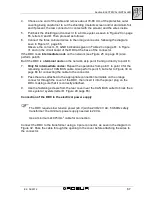
Pull back the shielding and connect it to a 4mm eyelet, as seen in Figure 29 on page
65, letters C and D. Then proceed as follows:
6.
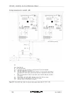
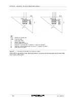
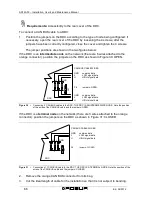
Connect the three coloured wires to the orange connector, following the diagram
seen in Figure 31, page 66.
Observe the correct L, H, GND indications given in Table 24 on page 61, in Figure
31 and on the circuit board of the DDC at the base of the connector.
If the DDC is an
intermediate node
on the network (see Figure 25 on page 61) also
perform point 6.
But if the DDC is a
terminal node
on the network, skip point 6 and go directly to point 8.
7.
Only for intermediate nodes:
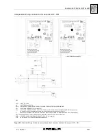
Repeat the operations from point 1 to point 4 for the
remaining section of CAN BUS cable. Also perform point 5, but refer to Figure 30 on
page 66 for connecting the cable to the connector.
8.
Pass the wires attached to the appropriate connection terminals on the orange
connector through the cover of the DDC, then insert it into the proper plug on the
DDC, making sure that it is correctly attached.
9.
Use the fastening screws from the rear cover near the CAN BUS outlet to block the 4
mm eyelet or eyelets (letter D, Figure 29 page 65).
Connection of the DDC to the electrical power supply
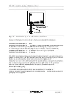
The DDC requires low tension power (24 V) with a 230/24 V AC, 50-60Hz safety
transformer; the minimum power supply needed is 20 VA.
Use a minimum 2x0.75mm
2
cable for connection.
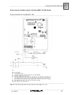
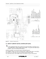
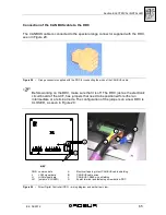
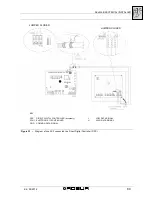
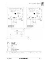
Connect the DDC to the transformer using a 4 pole connector, as seen in the diagram in
Figure 32. Pass the cable through the opening in the cover before attaching the wires to
the connector.
Summary of Contents for GA ACF60-00
Page 4: ......
Page 6: ...ACF60 00 Installation User s and Maintenance Manual 2 Ed 04 2012 ...
Page 56: ...ACF60 00 Installation User s and Maintenance Manual 52 Ed 04 2012 ...
Page 86: ...ACF60 00 Installation User s and Maintenance Manual 82 Ed 04 2012 ...
Page 91: ...APPENDIX Ed 04 2012 87 APPENDIX DECLARATION OF CONFORMITY ...
Page 92: ...ACF60 00 Installation User s and Maintenance Manual 88 Ed 04 2012 ...
Page 93: ...APPENDIX Ed 04 2012 89 ...
Page 94: ...ACF60 00 Installation User s and Maintenance Manual 90 Ed 04 2012 ...
Page 95: ......


