


Installation, Operation and Maintenance Manual– Ed.07/2005
21
EVOLUZIONE series natural gas/LPG heaters
3.3.6 GAS CHANGE
These operations must be carried out by
professionally qualified personnel
. Wrong or careless fitting and
installation of the gas circuit may cause dangerous gas leaks in the whole circuit and in particular in areas
that are tampered with. In addition, adequate sealants must be used on all connections.
If the type of gas indicated on the label does not correspond to that which is to be used, the appliance must be
converted and adapted to the type of gas that is going to be used.
To carry out this operation, proceed as follows:
A) Remove both the gas and electricity supply.
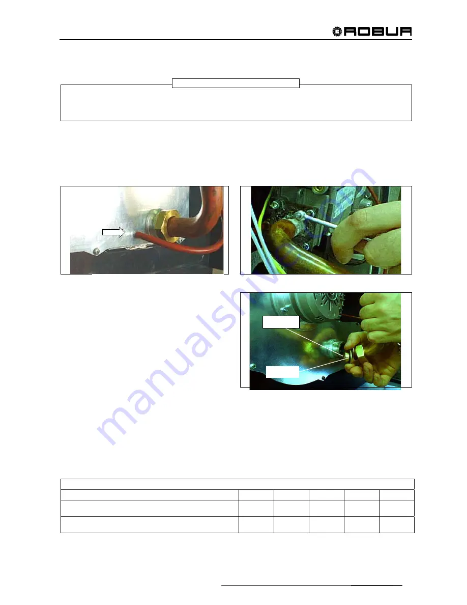
B) Unscrew the hexagonal nut that connects the gas pipe to the connector of the nozzle base (Figure 18).
Take care not to lose or damage the round internal seal.
Figure 18 –
USCITA DEL SEGNALE DI PRESSIONE GENERATO
DAL SOFFIATORE
Figure 19
C) Loosen, without removing, the 4 screws that fix
the gas supply pipe to the valve (Figure 19).
D) Move the gas pipe and extract the nozzle, with
the help of a screwdriver for leverage if
necessary (see Figure 20).
E) Remove the o-ring seal from the nozzle and fit
it to the new nozzle.
For the type of nozzle suitable for the model of
heater refer to Table 6.
F) Insert the new nozzle in its seating.
Figure 20
G) Refit the gas pipe, checking that the round seal in the metal nut and the square seal on the valve exit are
firmly in place. Tighten the nut to a locking torque of 62±2 Nm; tighten the valve screws and carry out
calibration checks.
H) Calibrate the appliance for the new gas type; adjusting the pressure to the burner as described in the
previous paragraph “Checking and adjusting operating gas pressure”.
I) While the appliance is in operation, check the sealing of all gas connections with soapy water or by
another suitable means, including those that have not been handled during the operation.
J) Replace the sticker indicating the type of gas applied on the appliance with one indicating the new type of
gas.
NATURAL GAS AND L.P.G. NOZZLES
E 32
E 42
E 43
E 52
E 72
Natural gas (G20)
diameter (mm)
stamped
code
4.60
108
5.50
119
5.90
074
7.20
120
10.3
121
LPG diameter
(mm)
stamped
code
3.50
117
4.25
122
4.50
123
5.40
073
7.50
124
Table 6
WARNING
G
UGELLO
O-RING
NOZZLE
EXIT OF PRESSURE SIGNAL GENERATED BY
BLOWER