background image

Tip

Tip

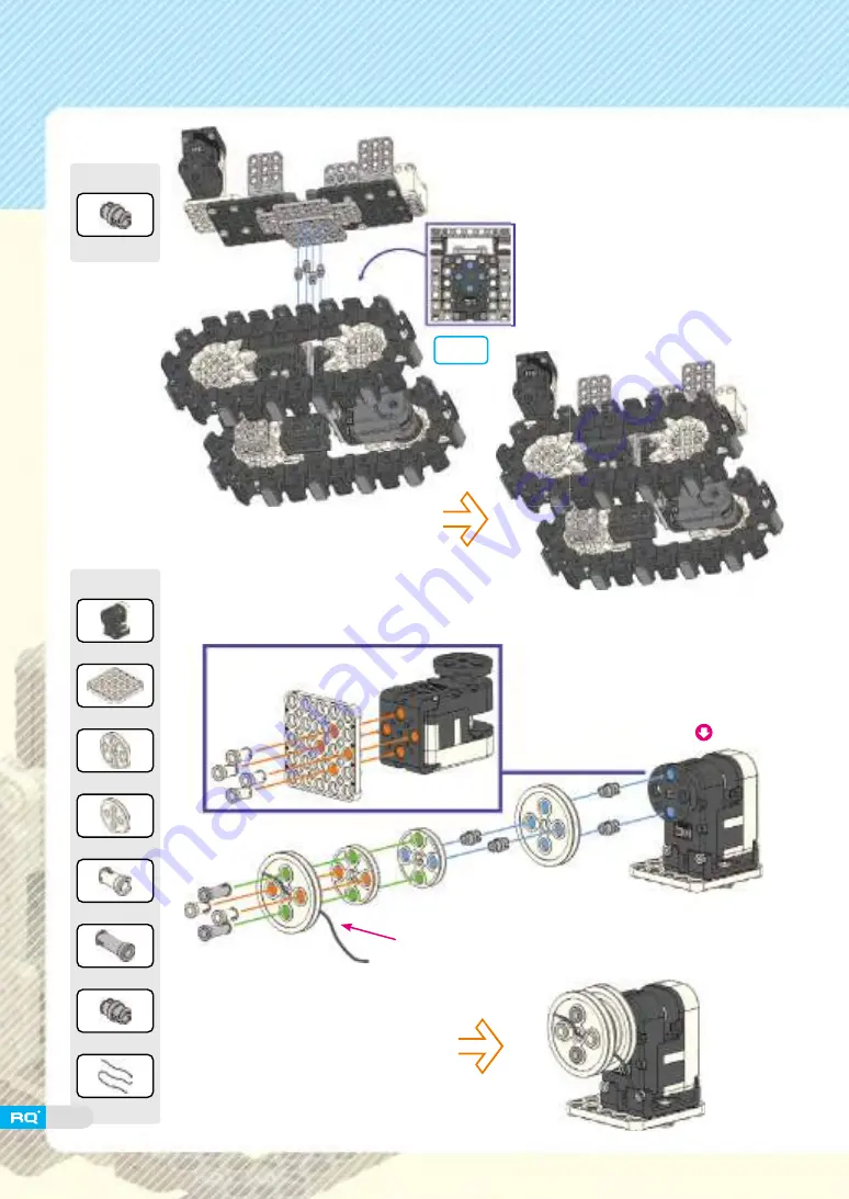
Double rivet X4

Smart servo (ID03) X1

5×5 frame X1

Small wheel X2

Wheel X2

2s rivet X6

3s rivet X2

Double rivet X4

String#2 X1

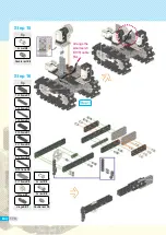
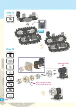
Step 13

Step 14

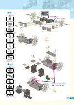
Step 8

Smart servo (ID03)

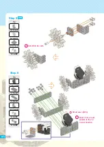
Put the string through the 
center hold of the wheels.

174

Summary of Contents for RQ PLUS 130

Page 1: ...ROBOT CONSTRUCTION KIT Construct more than 30 models with RQ 110 RQ 120 and RQ 130 ...

Page 2: ...List BASICS Tank Bot Four wheeled Bot Dino Vulcan Bot Forklift 06 12 30 48 68 88 ...

Page 3: ... My own Robot 1 Curling Bot Exploration Bot Crane Excavator Hu tank My own Robot 2 112 116 136 164 190 212 236 ...

Page 4: ...Ch1 Tank Bot Ch3 Dino Ch5 Forklift Ch2 Four wheeled Bot Ch4 Vulcan Bot Ch6 My own Robot 1 LED1 LED2 LED3 LED1 LED2 LED3 LED1 LED2 LED3 LED1 LED2 LED3 LED1 LED2 LED3 LED1 LED2 LED3 RQ 130 Robot 06 ...

Page 5: ...Ch7 Curling Bot Ch9 Crane Ch11 HU tank Ch8 Exploration Bot Ch10 Excavator Ch12 My own Robot 2 LED1 LED2 LED3 LED1 LED2 LED3 LED1 LED2 LED3 LED1 LED2 LED3 LED1 LED2 LED3 LED1 LED2 LED3 07 ...

Page 6: ... frame X2 Caterpillar X45 Ball frame X2 Small gear X2 Big gear X2 Small wheels X4 Wheel X2 Rubber ring X2 1 7 frame X2 2 9 frame X2 Rubber pad X23 3 5 L frame X2 1 8 frame X2 1 12 frame X2 2 15 frame X2 Spacer X4 3 5 frame X3 Locking ring X8 3 6 L frame X2 Boss gear frame X2 RQ 130 Part 08 ...

Page 7: ...Hinge B X3 Joint frame X2 String X2 Dice X1 Rubber ring X3 2s rivet 3s rivet IR sensor X2 Battery case X1 Serial board X1 Hinge A and Hinge B can be distinguished by its colors and letter A or B written on Be careful that Hinge A is white color but it is described as black color in RQ 120 and RQ 130 09 ...

Page 8: ...ight then connect to the power port of smart controller Warnings for Li poly battery and serial board Be sure to use two battery cases when you use a serial board Do not connect Li poly battery or other power device to the serial board Smart controller and smart servo can burn or be damaged Power off when the robot is not in use for a long period to prevent discharging Do not use damaged li poly b...

Page 9: ...er when the robot is not in use Place the robot parts away from baby or toddler In any case of swallowing parts contact doctor immediately Do not operate the robot near you or facing you Do not use a peeled off battery or damaged battery as it may lead to fire or burn skin Clean up all RQ parts after you build or play with your robot Power S W is built in the smart controller Insert power device A...

Page 10: ... because of the area touching the ground is wide Mmm But it looks like it would be difficult to change direction because of that Not at all You can just change the rotation speed and direction of caterpillar to easily change driving direction Plus it can turn the direction at a standstill Wow My lovely caterpillar There you go again Bulldozer space exploration robot tank Oh All the special cars mo...

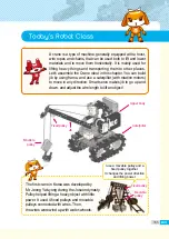
Page 11: ... and right side to detect the opposite robot s attack In this chapter we will assemble the Tank Bot and then play a game with it A tank is a large fighting vehicle for combat Modern tanks are strong mobile land weapons platforms mounting a large cannon in a revolving turret Revolving Turret Machine gun I use caterpillars instead of wheels so I can go anywhere Today s Robot Class 13 ...

Page 12: ...ll gear X2 Big gear X2 3 5 frame X2 3 7 frame X4 5 5 frame X2 3 16 slide frame X2 1 8 frame X4 1 12 frame X2 2 5 frame X2 2 7 frame X1 R motor ID30 X1 Smart servo ID00 01 02 X3 Battery case X1 Touch sensor X2 Prepare robot parts Tips To assemble the caterpillar hook a caterpillar ring to the next caterpillar as shown below Then insert rubber pads Rubber pads Robot Assembly 14 ...

Page 13: ...L frame X1 Spacer X1 Smart servo ID01 X1 1 8 frame X1 3 7 frame X1 3 5 L frame X1 3 6 L frame X1 Spacer X1 Small gear X1 Big gear X1 2s rivet X8 3s rivet X3 Double rivet X2 Small gear X1 Big gear X1 2s rivet X8 3s rivet X3 Double rivet X2 Smart servo ID01 Smart servo ID00 Step 1 15 ...

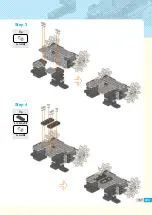
Page 14: ...Step 4 Tip Tip 3 5 frame X1 2s rivet X4 Smart controller X1 Battery case X1 Double rivet X4 Step 3 Smart servo ID01 Smart servo ID00 16 ...

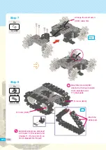
Page 15: ... 5 5 frame X2 2s rivet X8 Double rivet X4 Caterpillar X44 Rubber pad X22 Step 5 Smart servo ID00 Smart servo ID01 Step3 Assemble two caterpillar wheels Each wheel consists of 22 caterpillars and 11 rubber pads X2 17 ...

Page 16: ...ame X2 Front horn X1 Double rivet X8 2 7 frame X1 3 5 frame X1 3 6 L frame X2 3s rivet X4 Double rivet X4 Front and rear side of R motor ID30 are different Front side has the ID mark Front side Rear side R motor ID30 Step 7 Match home mark position 18 ...

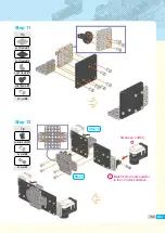
Page 17: ... 1 5 frame X1 1 8 frame X1 1 12 frame X1 2 5 frame X1 3 7 frame X1 3 16 slide frame X1 3 5 L frame X2 3 6 L frame X1 2s rivet X5 3s rivet X1 Double rivet X8 2s rivet X2 Step 9 Insert 2s rivets to the slide side of 3 16 slide frame 19 ...

Page 18: ...1 5 frame X1 1 8 frame X1 1 12 frame X1 2 5 frame X1 3 7 frame X1 3 16 slide frame X1 3 5 L frame X2 3 6 L frame X1 2s rivet X5 3s rivet X1 Double rivet X8 2s rivet X2 Step 11 Insert 2s rivets to the slide side of 3 16 slide frame 20 ...

Page 19: ...Step8 Step10 Step12 Step 14 Tip Tip 3s rivet X2 Smart servo ID02 X1 2s rivet X3 Step 13 Smart servo ID02 Match home mark 12 o clock direction position 21 ...

Page 20: ...Step 16 Tip Tip 3s rivet X4 2s rivet X1 Step 15 22 ...

Page 21: ...sor 1 Touch sensor 3 R motor ID30 Power device Lift 1 5 frame to connect 2s rivet Check the cable connection and direction Revolving turret Touch sensor 3 Touch sensor 1 Tip 2s rivet X1 Step 17 Step 18 Step6 23 ...

Page 22: ...Smart servo ID00 Smart servo ID01 Smart servo ID02 Tip Double rivet X4 Step 20 Step 19 24 ...

Page 23: ... Tank Bot is ready completion 25 ...

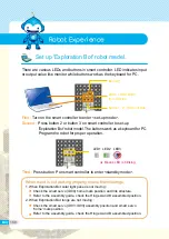
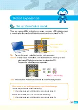
Page 24: ...work as a keyboard for PC Program the robot for proper operation Third Press button P on smart controller to enter standby mode LED1 LED2 LED3 When robot is not working properly check the followings 1 When machine gun of Tank Bot is not moving Refer to Step16 and Step17 then check rotation motor ID30 linkage 2 When revolving turret is not moving left or right Refer Step14 then check smart servo ID...

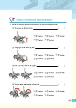
Page 25: ... should you press for following actions Choose from Example 1 Fire the machine gun 2 Stop the machine gun 3 Move revolving turret to the left 4 Move revolving turret to the right Check movement and assembly Example Tanks bulldozer and excavator bot use ⓐ A button ⓑ B button ⓒ button ⓓ button ⓔ button 27 ...

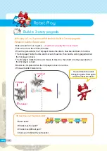
Page 26: ...uish from other team Place the Tank Bot outside the game panel when touch sensor is detected once Place the Tank Bot outside the game panel when the robot falls down or goes out the game panel Game time is 3 minutes and whoever has more Tank Bots available after 3 minutes wins the game Describe your Tank Bot Robot level What was the most fun about it What was the most difficult thing Check your ro...

Page 27: ...MEMO 29 ...

Page 28: ... Reflects small volume of light For example sunflower reflects yellow light and leaf reflects green light And that s how we see a sunflower Ah Black absorbs all lights so we see black And white reflects all light so we see white Right Infrared sensor uses this characteristic of light to detect an object Infrared sensor gives out light Infrared light to the object and measures the reflected light v...

Page 29: ...d vehicles so it can drive on rugged surface or an area with obstacles Also the Four wheeled Bot stops automatically when it detects cliff in front Four wheeled car means that driving power is delivered to each four wheels Compare to two wheeled car it has more driving power For this reason it is usable in slope or slippery road I am a jeep Some of amored or sports vehicles are a four wheeled car ...

Page 30: ... Wheel X4 Tire X4 Double rivet X30 3 5 frame X2 3 7 frame X5 3 9 frame X5 5 5 frame X2 1 7 frame X5 2 5 frame X2 2 7 frame X4 2 9 frame X5 Smart servo ID00 03 X4 Battery case X1 LED X2 IR sensor X1 Check the hinge A and B assembly position in Step15 Second Assemble as you fold hinge A and B inside Hinge A Hinge B Prepare robot parts Tips Robot Assembly 32 ...

Page 31: ...Step 2 Tip Tip 2 7 frame X2 2 9 frame X1 2 15 frame X2 3 5 frame X1 5 5 frame X1 3 6 L frame X2 2s rivet X18 1 7 frame X2 5 5 frame X1 3 6 L frame X1 2s rivet X4 3s rivet X8 Step 1 33 ...

Page 32: ...Step 4 Tip Tip IR sensor X1 1 5 frame X4 1 7 frame X2 3 9 frame X1 2 5 L frame X2 2s rivet X12 3s rivet X4 Double rivet X2 2 15 frame X2 3 7 frame X1 3s rivet X8 Step 3 Step2 X2 34 ...

Page 33: ...servo ID00 03 X4 2 5 L frame X2 Wheel X4 Tire X4 2s rivet X10 3s rivet X2 Double rivet X10 Battery case X1 Double rivet X4 Step 5 Insert rivets to the proper position carefully ID03 ID01 ID01 ID02 ID00 ID03 ID00 ID02 X2 35 ...

Page 34: ...Step 8 Tip Tip Smart controller X1 2 5 frame X2 2 7 frame X2 3 7 frame X4 3 6 L frame X1 2s rivet X20 2s rivet X6 Step 7 Step6 Insert 2s rivets first 36 ...

Page 35: ...Step 10 Tip Tip LED X1 2 9 frame X1 2 4 L frame X2 2 5 L frame X1 2s rivet X6 Double rivet X2 LED X1 2 9 frame X1 2 4 L frame X2 2 5 L frame X1 2s rivet X6 Double rivet X2 Step 9 37 ...

Page 36: ...12 Tip Tip 2 9 frame X2 2 4 L frame X2 Hinge A X2 Hinge B X2 2s rivet X6 3s rivet X4 Double rivet X2 1 7 frame X1 3 5 frame X1 3 9 frame X2 2s rivet X6 Step 11 Step10 Step9 Hinge B Hinge B Hinge A Hinge A 38 ...

Page 37: ...Step 14 Tip Tip 2s rivet X2 2s rivet X8 Step 13 Step11 39 ...

Page 38: ...Step 16 Tip Tip Double rivet X4 3 9 frame X1 Big U frame X1 2s rivet X2 Double rivet X2 Step 15 Step8 Hinge A Hinge B Assemble as you fold hinge A and B inside 40 ...

Page 39: ...Step 18 Tip Tip 2s rivet X2 3 9 frame X1 Big U frame X1 2s rivet X2 Double rivet X2 Step 17 Put down Four wheeled Bot body 41 ...

Page 40: ...Step 20 Step 19 LED1 LED2 LED2 LED1 ID00 ID02 ID01 ID03 Smart servo ID03 Smart servo ID00 Smart servo ID02 Smart servo ID01 IR sensor Power Check the cable connection and direction 42 ...

Page 41: ...ed Bot is ready completion Tip You can disassemble the Four wheeled Bot body by taking out 2s rivet as below Arrange cables from electronic parts inside of robot Disassemble body parts as you take out 2s rivets 43 ...

Page 42: ... Program the robot for proper operation Third Press button P on smart controller to enter standby mode Button P LED1 LED2 LED3 from left side Button 1 2 3 from left side LED1 LED2 LED3 Set up Four wheeled Bot robot model When robot is not working properly check the following 1 When robot is not moving forward backward at all Check power device and switch and robot model platform Refer to Step20 th...

Page 43: ...ote controller should be pressed to run each motion 1 Move forward and stop slowly 2 Move backward with melody when it detects a cliff Touch sensor IR sensor Rotation motor LED 1 We can see the certain object as the light is curved reflected 2 White Black absorbs light while White Black reflects all the light Check movement and assembly button button 45 ...

Page 44: ... team robot player to the out of game panel Game time is 3 minutes Whoever push more the opposite player s robot to the outside of game panel wins this game Describe your Four wheeled Bot today Robot level What was the most fun about it What was the most difficult thing Check your robot with your teacher Very easy Easy Average Difficult Very difficult Robot Play Why did you come to my home A team ...

Page 45: ...MEMO 47 ...

Page 46: ...es I thought all dinosaurs eat other animals and are violent Not exactly Carnivorous animals are violent but herbivorous animal are a bit gentler and milder Carnivorous animals eat other animals Yes they hunt and feed on meat So they have sharp teeth and claws And small and weak dinosaurs live together in a group to survive in the wild I am a triceratops I eat grass but I can defend myself with my...

Page 47: ...ino robot walks forward and moves in other directions The movie Jurassic Park is about a researcher extracting the DNA of dinosaurs from a mosquito and cloning dinosaurs You can see various dinosaurs from herbivorous animals to carnivorous animals such as tyrannosaurus Ⓒ Universal Pictures Amblin Entertainment Bang bang Boom boom Listen to the triceratops awesome heartbeat Today s Robot Class 49 ...

Page 48: ...rame X6 5 5 frame X1 7 7 frame X2 1 8 frame X1 2 5 frame X2 2 7 frame X4 2 9 frame X4 2 15 frame X3 R motor ID29 30 X2 Battery case X1 Smartservo ID00 03 X4 1 5 frame X2 You can find home mark on the smart servo and the rotation motor as below Match these home marks to the 12 o clock direction when you assemble the Dino robot To the 12 o clock direction To the 12 o clock direction Prepare robot pa...

Page 49: ...ble rivet X6 Smartservo ID02 X1 2 7 frame X2 3 9 frame X2 2s rivet X10 Step 1 Assemble Smart servo ID03 same as Smart servo ID02 Smart servo ID02 Smart servo ID00 X2 To the 12 o clock direction for smart servo Assemble Smart servo ID01 same as Smart servo ID00 Step 2 X2 51 ...

Page 50: ...X2 Double rivet X4 Battery caseX1 3 5 frame X2 3 7 frame X2 5 5 frame X1 3 5 L frame X1 3 6 L frame X2 2s rivet X12 Double rivet X4 Step 3 ID00 ID01 ID03 ID02 Step1 To the 12 o clock direction for all smart servos ID00 ID03 52 ...

Page 51: ...Step 6 Tip Tip 3s rivet X2 Double rivet X8 Smart controllerX1 3 5 frame X2 3 7 frame X2 2s rivet X6 Step 5 ID00 ID01 ID03 ID02 Step3 Check carefully 53 ...

Page 52: ...Step 8 Tip Tip 3s rivet X3 3s rivet X3 Step 7 Step5 54 ...

Page 53: ...Step 10 Tip Tip R motor ID29 30 X2 2 5 L frame X4 3 6 L frame X2 2s rivet X8 Double rivet X8 Double rivet X2 Step 9 R motor ID30 R motor ID29 R motor ID29 Step8 To the 12 o clock direction 55 ...

Page 54: ...Step 12 Tip Double rivet X2 Step 11 R motor ID30 R motor ID29 R motor ID30 Power Check the cable connection 56 ...

Page 55: ...ep 13 Smart servo ID01 Smart servo ID02 Smart servo ID00 Smart servo ID03 Tip 2 5 frame X2 2 15 frame X3 2s rivet X8 Step 14 Arrange all the cables for smart servo then connect to the smart controller 57 ...

Page 56: ...Step 16 Tip Tip 2 9 frame X2 3 5 L frame X2 2s rivet X8 1 5 frame X2 3 4 L frame X2 2s rivet X4 3s rivet X4 Step 15 Step13 58 ...

Page 57: ...Step 18 Tip Tip 3 3 frame X1 Double rivet X4 3 7 frame X2 7 7 frame X1 2 5 L frame X2 3 5 L frame X2 2s rivet X14 Step 17 59 ...

Page 58: ...Step 20 Tip Tip 1 8 frame X1 3 5 frame X2 3 9 frame X2 3 4 L frame X2 2s rivet X12 1 7 frame X2 2 9 frame X2 2 4 L frame X2 2s rivet X8 Step 19 X2 X2 60 ...

Page 59: ...Step 22 Tip Tip 3 4 L frame X2 Spacer X2 2s rivet X6 3s rivet X4 7 7 frame X1 2s rivet X4 Step 21 Step19 61 ...

Page 60: ...Step 24 Tip Tip 2s rivet X4 Double rivet X2 Step 23 Step17 Step18 62 ...

Page 61: ... Dino robot is ready completion 63 ...

Page 62: ...as a keyboard for PC Program the robot for proper operation Third Press button P on smart controller to enter standby mode Button P LED1 LED2 LED3 from left side Button 1 2 3 from left side When robot is not working properly check the following 1 When Dino robot is not working Check power connection and power switch then see the robot model platform 2 When Dino robot arms and legs are not moving R...

Page 63: ...oller button leads to following actions Choose from Example 1 Move two arms up and down 2 Stand with right leg 3 Spread two legs 4 Move forward when sound is detected Example ⓐ A button ⓑ B button ⓒ button ⓓ button ⓔ button button button ⓗ button ⓕ ⓖ 65 ...

Page 64: ...change playing area in second half time No foul for touching or disrupting another robot Possible to attack other robot Place to the original position when robot can t move Dinosaur soccer competition Describe your Dino robot Robot level What was the most fun about it What was the most difficult thing Check your robot with your teacher Very easy Easy Average Difficult Very difficult Robot Play Dis...

Page 65: ...MEMO 67 ...

Page 66: ...on tapes You can adjust the rotation speed of the second hand minute hand and hour hand with the gear size For example a small gear rotates several times while a big gear rotates once just like the second hand of clock Oh But the size of gears inside a clock is all different That s because the rotation speed of second minute and hour hand are different On the contrary a big gear rotates once when ...

Page 67: ...chine gun is rotated quickly There are more scientific principles behind the Vulcan Bot Let s find out Vulcan has 6 gunbarrels is normally equipped in tank and used for air defense for US Army The gun fires at 6 000 rounds per minute in maximum The entire process supply bullets load fire is done automatically I am Vulcan My name derived from a Roman god of fire Vulcan You can hang a rubber band on...

Page 68: ...9 frame X4 3 7 frame X6 3 6 L frame X6 5 5 frame X2 Small wheel X2 Wheel X6 Rubber ring X4 Tire X2 2 4 L frame X6 2 5 L frame X6 1 8 frame X4 2 5 frame X4 2 7 frame X4 2 9 frame X4 2 15 frame X4 R motor ID29 30 X2 Smart servo ID00 03 X4 Battery case X1 1 3 frame X4 Hang rubber bands like the picture below to shoot Rubber bullets Prepare robot parts Tips Robot Assembly 70 ...

Page 69: ... 3 4 L frame X2 2s rivet X8 Smartservo ID03 X1 2 15 frame X2 3 5 frame X2 3 4 L frame X2 3 6 L frameX1 2s rivet X6 3s rivet X4 Double rivet X2 Step 1 Smart servo ID03 Match home mark of smart servo to the 12 o clock direction 71 ...

Page 70: ...Step 4 Tip Tip Double rivet X4 1 7 frameX2 3 7 frame X1 3 9 frame X1 3 5 L frame X2 WheelX2 Tire X2 Spacer X2 2s rivet X6 3s rivet X2 Double rivet X2 Step 3 Step2 72 ...

Page 71: ...Step 6 Tip Tip 3 7 frame X2 3 9 frame X3 3s rivet X8 2s rivet X4 Step 5 73 ...

Page 72: ...29 Step 8 Tip Tip R motor ID29 30 X2 3 5 L frame X2 Wheel X4 Rubber ring X4 Front horn X2 2s rivet X6 bettery case X1 2 5 frame X2 3 5 frame X1 3 6 L frame X1 2s rivet X6 3 s rivet X2 Double rivet X2 Step 7 Double rivet X8 74 ...

Page 73: ...R motor ID30 R motor ID29 Step 10 Tip Tip 2s rivet X4 2 9 frame X4 3 5 L frame X2 3 6 L frame X2 3s rivet X8 Step 9 Step8 75 ...

Page 74: ...R motor ID30 R motor ID29 Step 12 Tip Tip Smart controller X1 2s rivet X4 Double rivet X2 2s rivet X4 Step 11 Step5 Step7 76 ...

Page 75: ...L frame X2 3 6 L frame X2 Spacer X2 Small gear X2 2s rivet X4 3s rivet X2 Double rivet X10 Smartservo ID02 X1 3 7 frame X1 2 4 L frame X2 2 5 L frame X2 2s rivet X12 Step 13 X2 Match home mark of smart servo to the 12 o clock direction Check for rivet position and direction 77 ...

Page 76: ... servo ID00 Smart servo ID01 Step 16 Tip Tip 1 3 frame X2 2 5 frame X2 2 15 frame X2 2s rivet X8 Double rivet X4 Smart servo ID00 01 X2 Big gear X2 2s rivet X10 Step 15 Insert 2s rivet to the frame first 78 ...

Page 77: ...Smart servo ID00 Smart servo ID02 Smart servo ID01 Smart servo ID00 Smart servo ID02 Step 18 Tip Tip 2s rivet X2 2s rivet X2 Step 17 Step13 79 ...

Page 78: ...Assemble two sets Step 20 Tip Tip 1 8 frame X2 5 5 frame X1 2 5 L frame X2 Small wheel X1 2s rivet X4 Double rivet X6 3 5 frame X1 3s rivet X2 Step 19 X2 X2 80 ...

Page 79: ...Vulcan part Revolving turret Step 22 Step 21 Tip Tip Double rivet X4 2 7 frame X2 2 4 L frame X2 2s rivet X4 Double rivet X4 X2 X2 Step19 Assemble two sets 81 ...

Page 80: ...Smart servo ID02 Smart servo ID01 Smart servo ID00 Smart servo ID03 R motor ID29 R motor ID30 Power Step 24 Step 23 Step12 Step22 Check for cable connection and position 82 ...

Page 81: ... Vulcan Bot is ready completion Tip Double rivet X4 Step 25 83 ...

Page 82: ...rk as a keyboard for PC Program the robot for proper operation Third Press button P on smart controller to enter standby mode Button P LED1 LED2 LED3 from left side Button 1 2 3 from left side When robot is not working properly check the followings 1 When the revolving turret of Vulcan Bot is not moving Refer to Step13 then check smart servo ID and home position 2 When the vulcan of Vulcan Bot is ...

Page 83: ... of the gears and pulleys are rotating In this case draw an arrow near the other gear and pulley to indicate the rotating direction 1 3 2 4 2 Which IR remote controller button leads to this action button button Go forward and rotate Vulcan Stop the rotation of Vulcan button button 85 ...

Page 84: ...lving turret to left Revolving turret to right Revolving turret to center START 25cm Rubber band bullet Describe Vulcan Bot Robot level What was the most fun about it What was the most difficult thing Check your robot with your teacher Very easy Easy Average Difficult Very difficult Robot Play Fold paper as below as targets then place the Vulcan Bot in START position Fire towards the targets with ...

Page 85: ...MEMO 87 ...

Page 86: ...t sure what a fixed pulley is A fixed pulley changes the direction of the force on a rope or belt Forklift is a heavy machinery vehicle used to load and unload heavy things Forklift uses a fixed pulley and lifting chain to lift the fork up and down easily Fixed pulley Lifting chain Direction of force Direction of force Fork It s more comfortable when you use a fixed pulley to lift up an object Wha...

Page 87: ... Plus the smart servo can make it go forward and backward Let s assemble a forklift and find out how it can perform Forklift is used to move very heavy objects heavier than 1 ton Forklift uses a fixed pulley and chain so that it can easily lift an object up and down A fixed pulley changes the direction of the force on a rope or belt that moves along its circumference I can easily move any heavy th...

Page 88: ...l gear X2 3s rivet X20 2s rivet X150 3 6 L frame X5 Big gear X4 Double rivet X60 2 5 frame X4 2 7 frame X2 3 7 frame X5 2 9 frame X4 5 5 frame X4 3 9 frame X6 2 15 frame X6 7 7 frame X2 3 3 frame X3 3 16 frame X2 Smart servo ID00 03 X4 Battery case X1 1 5 frame X2 1 8 frame X4 Forklift uses a caterpillar to lift up and down so it should be assembled as shown in the picture Prepare robot parts Tips...

Page 89: ... Tip Tip Tip 2 15 frame X2 Ball frame X1 2s rivet X4 Double rivet X2 Small wheel X2 Wheel X1 Tire X1 Small gear X1 Double rivet X4 3 3 frame X1 5 5 frame X2 7 7 frame X1 3 6 L frame X1 2s rivet X12 X2 Assemble two sets 91 ...

Page 90: ...tep 4 Tip Tip 2 7 frame X1 2 15 frame X1 3 5 frame X1 3 6 L frame X2 Locking ring X2 Small axle X1 2s rivet X8 2 7 frame X1 2 15 frame X1 3 5 frame X1 3 6 L frame X2 Locking ring X2 Small axle X1 2s rivet X8 92 ...

Page 91: ...Step 7 Step 6 Tip Tip 2 9 frame X2 3 7 frame X1 7 7 frame X1 3 5 L frame X2 Double rivet X12 2s rivet X4 Step2 Step4 Step5 93 ...

Page 92: ...ip Tip Smart controller X1 2 5 frame X2 2 4 L frame X4 2s rivet X12 Double rivet X2 Smartservo ID00 01 X2 Big gear X2 2s rivet X12 Smart servo ID01 Smart servo ID00 Smart servo ID01 Assemble double rivet at the end 94 ...

Page 93: ...Step 11 Step 10 Tip Tip 3 3 frame X1 3 9 frame X2 Ball frame X1 2s rivet X6 Double rivet X6 Battery case X1 2 5 L frame X2 2s rivet X4 Double rivet X4 95 ...

Page 94: ...Step 13 Step 12 Tip Tip 2s rivet X4 2s rivet X8 Step6 96 ...

Page 95: ...Step 15 Step 14 Tip Tip 1 5 frame X2 1 12 frame X2 3 9 frame X4 Caterpillar X20 2s rivet X8 Double rivet X22 3 7 frame X1 3 5 L frame X2 2s rivet X8 Assemble first 97 ...

Page 96: ...6 Tip Tip Smartservo ID02 03 X2 3 7 frame X2 2s rivet X8 3 4 L frame X2 3 16 slide frame X2 2s rivet X4 Double rivet X4 Smart servo ID02 Smart servo ID03 Check the home mark of smart servo and front horn carefully 98 ...

Page 97: ...Step 19 Step 18 Tip Tip 3 5 frame X2 Big gear X2 2s rivet X8 2 15 frame X2 3 5 L frame X2 3s rivet X8 Smart servo ID02 Smart servo ID03 Check the home mark of smart servo and front horn carefully 99 ...

Page 98: ...Step 21 Step 20 Tip Tip 2s rivet X2 2s rivet X2 Smart servo ID02 Smart servo ID03 Step16 Step16 Insert the teeth of gear to caterpillar Insert the teeth of gear to caterpillar 100 ...

Page 99: ...Step 23 Step 22 Tip 5 5 frame X2 2s rivet X8 Smart servo ID03 Smart servo ID02 Power Step14 101 ...

Page 100: ...Step 24 Step 25 Tip 3 3 frame X1 3s rivet X2 Smart servo ID03 Smart servo ID01 Smart servo ID00 ID01 ID03 ID02 Smart servo ID02 Step22 102 ...

Page 101: ...Step 27 Step 26 Tip Tip 2 9 frame X2 3 7 frame X1 2 5 L frame X2 3 4 L frame X2 2s rivet X8 3s rivet X4 2s rivet X4 X2 103 ...

Page 102: ...Step 29 Step 28 Tip Tip 2 5 frame X2 3s rivet X6 1 8 frame X4 Rubber pad X4 2s rivet X8 Fork for forklift Step26 104 ...

Page 103: ... Forklift robot is ready completion Do not force the forklift to move It may damage the smart servo and gear 105 ...

Page 104: ...t models in RQ 130 If a robot s operation is weak add another battery case If a robot s operation is normal there is no need to add another battery case Additional parts Battery case X1 Serial board X1 Double rivet X2 Step 1 Take out the battery case on the robot first 106 ...

Page 105: ...Step 3 Step 2 Tip Tip Serial board X1 Double rivet X2 Battery case X2 Double rivet X2 Connect the cables of battery cases to the serial board 107 ...

Page 106: ... Complete of an additional battery case for Forklift Step 4 completion 108 ...

Page 107: ...on Third Press button P on smart controller to enter standby mode Setup Forklift robot model When robot is not working properly check the following 1 When Forklift robot is not moving Check the power connection and switch and then check the robot model platform 2 When fork of Forklift robot is not moving up and down Refer to Step17 and Step22 check smart servo ID and home mark direction Refer to S...

Page 108: ...r button with corresponding action 2 Press button together and write which action it leads to ⓐ A button Fork goes up Fork moves to the center Fork goes down Fork goes up little by little Fork goes down little by little ⓑ B button ⓒ button ⓓ button ⓔ button 110 ...

Page 109: ...s in center and start from each player s side Move pallets to each player s goal line Game time is 3 minutes Whoever moves more pallets wins Assemble many pallets to play with your friends Move pallet You cannot get out of the game panel during the game Stand pallet up Describe Forklift robot Robot level What was the most fun about it What was the most difficult thing Check your robot with your te...

Page 110: ...everal times quickly while the big gear rotates once And have that power rotate the big gear and the small gear Put on a rubber string to the big gear and the small gear to send driving power And add a motors so the bicycle can move by itself No need to step on the pedals When rotates once Handlebar grip Saddle seat Pedal Big gear Small gear Chain It rotates several times Motor I think we could us...

Page 111: ...My own robot PART1 My robot is called Why did you build this robot How did you build your robot What kind of function does it have Problem Solution Something you learned while building the robot Creative Robot Class 113 ...

Page 112: ...ure of your own robot below Describe Forklift robot Robot level What was the most fun about it What was the most difficult thing Check your robot with your teacher Very easy Easy Average Difficult Very difficult 114 ...

Page 113: ...MEMO 115 ...

Page 114: ... broom That s called Curling broom It controls the speed of stone to move forward Frictional force refers to the force that interrupts the movement of an object That s right Frictional force becomes greater when the floor surface is rough For example you can easily walk on the road with your shoes But it s a different story when you are walking on ice because there is less friction Stone goes furt...

Page 115: ...ng Bot game with these functions Curling is a sport in which players slide stones on a sheet of ice towards a target area which is segmented into four concentric rings Two teams each of four players take turns sliding heavy polished granite stones also called rocks across the ice curling sheet towards the house a circular target marked on the ice Friction force between ice and stone will decrease ...

Page 116: ...L frame X8 Ball frame X2 1 5 frame X2 3 5 frame X4 2 5 frame X6 3 7 frame X3 2 7 frame X2 3 9 frame X5 2 15 frame X4 5 5 frame X2 R motor ID29 30 X2 Smart servo ID00 03 X4 Battery case X1 Touch sensor X1 Prepare robot parts Tips Make a knot for short string and rubber band to use for Curling Bot assembly Make a knot after hanging the string onto joint frame Hang a rubber band Wind up a rubber band...

Page 117: ...2 2 5 frame X1 3 6 L frame X1 Joint frame X1 2s rivet X8 Double rivet X2 3s rivet X4 Double rivet X4 R motor ID30 R motor ID29 Smart servo ID00 Smart servo ID01 home mark position goes to 3 o clock position Smart servo ID00 home mark position goes to 12 o clock position Smart servo ID01 Step 1 Step 2 119 ...

Page 118: ...s rivet X2 Double rivet X3 1 3 frame X1 3 5 L frame X1 3s rivet X2 Step 3 Step1 Step 4 R motor ID29 Smart servo ID01 R motor ID30 Smart servo ID00 Smart servo ID01 Smart servo ID00 R motor ID30 R motor ID29 120 ...

Page 119: ...Tip Tip 3 5 frame X1 3 7 frame X2 3 9 frame X1 Ball frame X2 2s rivet X4 3s rivet X4 Double rivet X4 2s rivet X4 Step 5 Step 6 Step4 R motor ID29 Smart servo ID01 Smart servo ID00 R motor ID30 121 ...

Page 120: ...tservo ID02 03 X2 1 3 frame X2 3 5 L frame X4 3 6 L frame X4 2s rivet X8 3s rivet X4 Double rivet X8 2s rivet X6 3s rivet X4 Double rivet X4 Step 7 Step 8 Smart servo ID02 Smart servo ID03 Smart servo ID02 ID03 home mark to the 12 o clock position Check the 3 5 3 6 L frame position for assembly 122 ...

Page 121: ...e X2 2 5 frame X4 2 7 frame X2 3 9 frame X2 Rightangleframe X2 Rubber pad X2 2s rivet X12 3s rivet X2 2s rivet X20 Double rivet X4 Step 9 Step 10 Smart servo ID02 Smart servo ID03 Smart servo ID02 Smart servo ID03 123 ...

Page 122: ...Tip Tip 2s rivet X2 2s rivet X2 Step 11 Step 12 Step7 Smart servo ID02 Smart servo ID03 It becomes the tongs 124 ...

Page 123: ...e X2 3 7 frame X1 3 6 L frame X1 2s rivet X6 2 5 frame X1 2s rivet X2 Step 13 Step 14 It becomes the shoot bar Smart servo ID02 Smart servo ID03 Assemble a 2 5 frame after connecting a 2 15 frame to the tongs Step12 125 ...

Page 124: ...geA X2 2s rivet X1 Double rivet X1 String X1 1 3 frame X1 3s rivet X2 Step 15 Step 16 Wind up to hinge A and make a knot Insert a string into hinge A then fix the center of string 25cm with hinge A 25cm Step14 126 ...

Page 125: ...Tip Tip 1 3 frame X2 Spacer X2 2s rivet X6 3s rivet X2 Rubber band X1 Step 17 Step 18 Insert a string to joint frame then make a knot Hang the rubber band Hang a rubber band Wind up the rubber Step6 127 ...

Page 126: ...Tip Tip 3 4 L frame X2 2s rivet X4 3 4 L frame X2 2s rivet X4 Step 19 Step 20 128 ...

Page 127: ...Tip Tip Smart controller X1 Battery case X1 2 15 frame X2 2s rivet X4 Double rivet X4 Double rivet X4 Step 21 Step 22 Step20 129 ...

Page 128: ...Step 23 Step 24 Click the cable connection and position R motor ID29 Power Touch sensor Smart servo ID00 Smart servo ID01 Smart servo ID03 Smart servo ID02 R motor ID30 130 ...

Page 129: ... Curling Bot is ready completion 131 ...

Page 130: ...d for PC Program the robot for proper operation Third Press button P on smart controller to enter standby mode LED1 LED2 LED3 When robot is not working properly check the followings 1 When shoot bar of Curling Bot is not moving Check the smart servo ID00 ID01 and touch sensor connected position Check the string and rubber band knot 2 When tongs of Curling Bot is not moving Check the smart servo ID...

Page 131: ...ollows the combination of given buttons Check movement and assembly 1 A button 1 button 2 button 2 B button 3 button 4 button 5 button Pick up an object Put down an object Spread tongs little by little Shoot and re load Narrow the gap of tongs little by little 133 ...

Page 132: ...nds and put a mark on one team for distinguishment You get 2 points when the dice makes it into the center circle And you get 1 point when the dice is placed on the center circle line You can push other team s dice with your dice Discuss with friends to win the game Describe your Curling Bot Robot level What is most fun part What is most difficult part Check your robot with your teacher Very easy ...

Page 133: ...MEMO 135 ...

Page 134: ...eep beep Eek This rock is too heavy I m giving up on carrying it Beep beep What The gravity in the Moon is just one sixth of the earth s So it should be light to carry It s because it collided with various meteors in the space And we call these marks crater There s no water and air in the moon Human can t live without them And same for animals and plants How come there isn t anyone earth Let s fin...

Page 135: ... an object and has arms to pick up an object and move to another place It also can freely move in any direction by using the rotation motors Curiosity is car sized robotic rover exploring Gale Crater on Mars as part of NASA s mission landed on August 6th 2012 in Mars It has high tech sensors and experiment equipments to analyze climate temperature as well as stones soils to check whether the creat...

Page 136: ... frame X2 Big U frame X2 Double rivet X50 3s rivet X42 2s rivet X148 Hinge B X7 Hinge A X7 Spacer X9 Rubber pad X3 5 5 frame X4 7 7 frame X2 Right angle frame X1 Opposite angle frame X1 3 4 L frame X4 2 9 frame X4 2 15 frame X4 3 3 frame X3 3 5 frame X8 3 7 frame X6 Prepare robot parts Tips Check the home mark position of smart servo below Smart servo ID00 ID01 to the 3 o clock position Smart serv...

Page 137: ...p Tip Smartservo ID00 X1 3 7 frame X1 5 5 frame X2 3 6 L frame X1 2s rivet X6 3s rivet X4 2 15 frame X2 3 5 L frame X4 2s rivet X8 3s rivet X4 Step 1 Step 2 Smart servo ID00 To the 3 o clock position 139 ...

Page 138: ...2 Wheel X2 Spacer X2 2s rivet X4 3s rivet X2 R motor ID29 30 X2 2 7 frame X1 2 9 frame X2 7 7 frame X1 Wheel X2 Rubber ring X2 Spacer X2 2s rivet X4 3s rivet X2 Double rivet X4 Step 3 Step 4 R motor ID30 R motor ID29 140 ...

Page 139: ...Tip Tip 2 15 frame X2 3 7 frame X1 3 9 frame X2 5 5 frame X2 3 6 L frame X1 2s rivet X12 3s rivet X4 3 4 L frame X2 2s rivet X8 Step 5 Step 6 141 ...

Page 140: ...ame X2 3 5 L frame X2 Wheel X2 Spacer X2 2s rivet X8 3s rivet X2 Smartservo ID01 X1 Joint frame X1 2s rivet X2 Double rivet X2 Step 7 Step 8 To the 3 o clock position Smart servo ID01 Check joint frame direction 142 ...

Page 141: ...Tip Tip 2s rivet X3 Double rivet X1 2s rivet X4 Step 9 Step 10 R motor ID30 R motor ID29 Smart servo ID00 Smart servo ID01 Step9 Step4 Step3 Step7 143 ...

Page 142: ...Tip Tip Battery case X1 Double rivet X4 2s rivet X8 Step 11 Step 12 144 ...

Page 143: ... 5 frame X2 3 7 frame X1 3 9 frame X1 2s rivet X8 3s rivet X2 1 3 frame X2 1 5 frame X2 2 5 frame X2 Hinge A X2 Hinge B X2 2s rivet X4 Double rivet X10 Step 13 Step 14 X2 Hinge B Hinge A Hinge A Hinge B Assemble two sets 145 ...

Page 144: ...X4 Hinge B X4 2s rivet X4 Double rivet X13 3s rivet X2 Double rivet X7 Step 15 Step 16 Hinge B Hinge B Hinge B Hinge B Hinge A Hinge A Hinge A Hinge A Check the Hinge A and Hinge B assembly direction It becomes the solar light panel Step12 146 ...

Page 145: ...Tip Tip 2 5 frame X1 3 7 frame X1 2s rivet X2 3s rivet X2 2 9 frame X1 3 7 frame X1 3 6 L frame X3 Big U frame X2 2s rivet X14 Step 17 Step 18 147 ...

Page 146: ...Tip Tip 7 7 frame X1 2s rivet X6 2s rivet X4 Step 19 Step 20 Step17 148 ...

Page 147: ...me X2 3 5 frame X1 3 5 L frame X2 Rubber pad X3 1 3 frame X1 1 5 frame X2 1 7 frame X1 Spacer X1 Hinge A X1 Hinge B X1 2s rivet X1 3s rivet X2 Double rivet X4 It becomes the tongs Hinge A Hinge B 2s rivet X9 Double rivet X1 Step 21 Step 22 149 ...

Page 148: ... 6 L frame X2 Joint frame X1 3s rivet X5 3 3 frame X1 Spacer X2 2s rivet X1 3s rivet X4 Step 23 Step 24 Step22 Put down the Hinge B to the right angle and then connect with 2s rivet To the 12 o clock position Smart servo ID03 150 ...

Page 149: ... sensor X2 3 5 frame X1 3 9 frame X1 3 4 L frame X2 2s rivet X8 Double rivet X4 3s rivet X4 Step 25 Step 26 Step24 Smart servo ID02 home mark position to the 12 o clock positon Smart servo ID02 Smart servo ID02 Smart servo ID03 151 ...

Page 150: ...Tip Tip 3s rivet X1 1 12 frame X1 2 9 frame X1 Right angle frame X1 OppositeangleframeX1 2s rivet X6 Step 27 Step 28 Put down the tongs Refer to Step 29 Step20 152 ...

Page 151: ...mart controller X1 Step 29 Step 30 Step27 Check the cable connection and direction R motor ID29 R motor ID30 IR sensor 2 IR sensor 4 IR sensor 4 Power Connect cables to the smart controllers and then assemble in Step 32 153 ...

Page 152: ...Tip 2s rivet X4 Step 31 Step 32 Smart servo ID00 Smart servo ID01 Smart servo ID03 Smart servo ID02 154 ...

Page 153: ... Exploration Bot is ready completion Do not fold the solar light panel by force 155 ...

Page 154: ...models in RQ 130 If a robot s operation is weak add another battery case If a robot s operation is normal there is no need to add another battery case Additional parts Battery case X1 Serial board X1 Double rivet X4 1 5 frame X4 Tip Serial board X1 Double rivet X2 Step 1 156 ...

Page 155: ...Take out the smart controller and connect the serial board then reassemble 157 ...

Page 156: ...Tip Tip 2s rivet X4 Battery case X4 1 5 frame X1 Double rivet X4 Step 4 Step 5 158 ...

Page 157: ...Step 6 Complete of an additional battery case for Exploration Bot completion 159 ...

Page 158: ...utton P on smart controller to enter standby mode LED1 LED2 LED3 When robot is not working properly check the followings 1 When Exploration Bot solar light panel is not moving Check the smart servo ID00 home mark position and link structure Refer to the assembly guide check the Hinge A and B assembled position 2 When Exploration Bot tongs are not moving Check the smart servo ID01 ID03 assembly pos...

Page 159: ...y A button B button button button button A button B button button button button A button B button button button button A button B button button button button 1 Tongs go up little by little 2 Tongs go down little by little 3 Pick up or put down an object 4 Tongs rotate backward or forward 161 ...

Page 160: ...a when the 1st player is back The 3rd player holds the dice and moves to blue line then build a 3 story pagoda when the 2nd player is back Mission is completed when the 3rd player is back to red line Whoever builds it faster wins Describe your Exploration Bot Robot level What is most fun part What is most difficult part Check your robot with your teacher Very easy Easy Average Difficult Very diffi...

Page 161: ...MEMO 163 ...

Page 162: ...able pulley reduces the weight to half compared with carrying with your hand Right So the crane is used for construction to move heavy materials When you pull the string of the fixed pulley down then the directin of power changes as the object is lifted Direction the object will move Direction of power The top part uses a fixed pulley and the bottom part uses a movable pulley Use of these two pull...

Page 163: ...to move in any direction Smart servo makes jib to go up and down and adjust the wire length to lift an object The first crane in Korea was developed by Mr Jeong Yak yong during the Joseon dynasty Pulley helped lifting a heavy object with little power It used 4 fixed pulleys and movable pulleys connected with wires Then the wires were wind up with water wheels I use a movable pulley and a fixed pul...

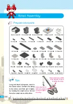
Page 164: ...ing 2 X1 String 1 X1 Hinge B X1 Hinge A X2 7 7 frame X2 2 4 L frame X2 3 5 L frame X6 3 6 L frame X6 Small wheel X4 2 15 frame X4 3 3 frame X4 3 5 frame X9 3 7 frame X4 3 9 frame X3 Prepare robot parts Tips Long and short strings are used in the Crane robot Connect the string to the robot and then pull it tightly by rotating the smart servo Do not force the smart servo at this time Rotate smart se...

Page 165: ...Tip Tip 2s rivet X4 2 5 frame X2 2s rivet X6 Step 3 Step 4 167 ...

Page 166: ...lar wheels Each wheel consists of 22 caterpillars and 11 rubber pads Arrange the smart servo ID00 cable first Attach the rubber pad R motor ID30 Caterpillar wheels are also used in Chapter 10 Excavator and Chapter 11 Hu tank robot so do not disassemble this part X2 R motor ID29 Step4 168 ...

Page 167: ...5 frame X1 7 7 frame X1 3 6 L frame X1 Joint frame X1 2s rivet X9 Smartservo ID01 X1 2s rivet X4 3s rivet X1 Step 11 Step 12 Step10 Step9 Smart servo ID01 Match home mark position to the 12 o clock direction 169 ...

Page 168: ...X2 1 3 frame X1 1 5 frame X1 1 8 frame X1 2 5 frame X1 2 7 frame X2 2 9 frame X2 2 15 frame X2 3 7 frame X2 Wheel X1 Hinge B X1 2s rivet X8 3s rivet X8 Double rivet X3 Step 15 Step 16 Step13 Arrange the smart servo ID00 cable first 170 ...

Page 169: ... 3 5 frame X2 3 6 L frame X2 Small wheel X2 Big gear X2 2s rivet X8 3s rivet X8 3 3 frame X2 3 9 frame X1 2 4 L frame X2 Big U frame X2 2s rivet X12 Step 1 Step 2 R motor ID30 R motor ID29 Arrange the rotation motor cable before assembly 171 ...

Page 170: ...ar X1 Gear boss frame X1 2s rivet X5 Smart servo ID00 X1 3 5 frame X3 3 9 frame X1 3 6 L frame X1 2s rivet X3 3s rivet X8 Step 5 Step 6 X2 Assemble two sets Match home mark position to the 12 o clock direction Smart servo ID00 172 ...

Page 171: ...Tip Tip 1 7 frame X2 3 5 frame X3 3 9 frame X1 2s rivet X4 3s rivet X4 Touch sensor X1 7 7 frame X1 3 5 L frame X2 3 6 L frame X1 2s rivet X6 Double rivet X2 Step 9 Step 10 173 ...

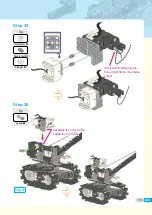
Page 172: ...e rivet X4 Smartservo ID03 X1 5 5 frame X1 Small wheel X2 Wheel X2 2s rivet X6 3s rivet X2 Double rivet X4 String 2 X1 Step 13 Step 14 Step8 Smart servo ID03 Put the string through the center hold of the wheels 174 ...

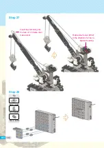
Page 173: ...Tip Tip 2 15 frame X2 2s rivet X8 2s rivet X2 Step 17 Step 18 Step15 175 ...

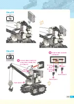
Page 174: ...Tip Tip 1 5 frame X2 2 5 frame X2 3 3 frame X1 3s rivet X5 5 5 frame X2 Wheel X1 3s rivet X2 Double rivet X2 Step 19 Step 20 Assemble from first then 176 ...

Page 175: ...et X9 Step 21 Step 22 Hang the string to the pulley and insert it into the hole of Hinge Fixed pulley Movable pulley ⓒ Rotate smart servo ID03 to the direction of arrow to tighten the string ⓐ Make a knot as winding up the long string to Hinge ⓑ Make space about 5cm from the ground Step18 177 ...

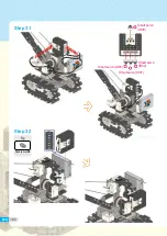
Page 176: ...p 2s rivet X4 Smartservo ID02 X1 3 5 frame X1 3 5 L frame X1 3 6 L frame X1 Joint frame X1 2s rivet X6 3s rivet X3 Double rivet X2 Step 23 Step 24 Step21 Arrange the rotation motor cable Smart servo ID02 178 ...

Page 177: ...ip Tip Touch sensor X1 Double rivet X2 String 1 X1 3s rivet X3 Step 25 Step 26 Insert a short string into the hole of joint frame then make a knot Assemble the 3 5 L frame beside the 3 7 frame Step23 179 ...

Page 178: ... 27 Insert the short string into the hole of 1 5 frame then make a knot Rotate smart servo ID02 to the direction of arrow to tighten the string Tip Battery case X1 3 5 L frame X1 Double rivet X4 Step 28 180 ...

Page 179: ...roller X1 Step 29 Step 30 Connect cables of electronics to the smart controller then go to Step 32 Check for cable connection and direction Touch sensor 3 Touch sensor 1 R motor ID29 Power Touch sensor 3 Touch sensor 1 R motor ID30 181 ...

Page 180: ...Step 31 Tip Double rivet X2 Step 32 Smart servo ID00 Smart servo ID03 Smart servo ID02 Smart servo ID01 182 ...

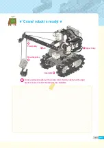
Page 181: ... is ready completion Fixed pulley Movable pulley Caterpillar Jib Upper body Do not exercise strong force to the Crane robot Hold the robot when the upper part is connected or disconnected from the caterpillars 183 ...

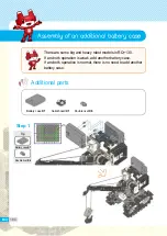
Page 182: ... robot models in RQ 130 If a robot s operation is weak add another battery case If a robot s operation is normal there is no need to add another battery case Additional parts Battery case X1 Serial board X1 Double rivet X6 Tip Battery case X1 Double rivet X4 Step 1 184 ...

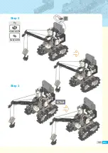
Page 183: ...Tip Serial board X1 Double rivet X2 Step 2 Step 3 185 ...

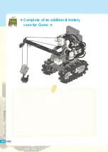
Page 184: ... Complete of an additional battery case for Crane completion 186 ...

Page 185: ...work as a keyboard for PC Program the robot for proper operation Third Press button P on smart controller to enter standby mode LED1 LED2 LED3 When robot is not working properly check the followings 1 When the jib of Crane robot is not moving Check the smart servo ID02 and its connection to string 1 2 When the movable pulley of Crane robot is not moving Check the smart servo ID03 and its connectio...

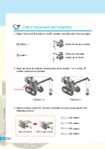
Page 186: ...1 or 3 on the IR remote controller is pressed 3 Which button on the IR remote controller should you press for the following action Check movement and assembly A button B button Move the jib up or down Move the movable pulley up or down Button 1 Upper body Button 3 button button button button Move forward Then stops slowly 188 ...

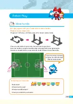
Page 187: ...ng the movable pulley to the goal line B when game begins Mission is completed when you put down the hurdle Whoever moves faster wins Describe your Crane robot Robot level What is most fun part What is most difficult part Check your robot with your teacher Very easy Easy Average Difficult Very difficult Robot Play Move hurdle You can t touch the robot during the game You can fix the robot when the...

Page 188: ...all syringe affects entire big syringe Those tubes work like the piston of syringe to dig the ground and carry the soil Look Excavator has a thin metal tube and thick metal tube A small syringe full with liquid is connected with a big syringe with liquid filled to half way It moves with the hydraulic pump When you press the piston of the small syringe the liquid moves to the big syringe so the pis...

Page 189: ...otor to move with caterpillars and the upper body and arm part consist of a smart servo and link structure Let s assemble the excavator robot and find out which part is same or different from a real excavator Excavators are also called diggers mechanical shovels or 360 degree excavators and mainly handle digging of trenches holes and foundations It consists of the upper body and the arm I can dig ...

Page 190: ...30 min direction for smart servo ID03 smart servo ID03 Robot Assembly 2 9 frame X2 2 7 frame X1 2 5 frame X5 1 12 frame X2 1 8 frame X2 1 7 frame X3 2 15 frame X2 7 7 frame X2 Small wheel X2 Caterpillar X44 Rubber pad X22 Locking ring X2 Small axie X1 Big gear X4 Gear boss frame X2 Double rivet X33 3s rivet X44 2s rivet X131 Big U frame X2 Hinge B X1 Hinge A X1 2 4 L frame X6 2 5 L frame X5 3 4 L ...

Page 191: ...lar s wheel part Smart servo ID00 home mark is to the 12 o clock From Step 1 to Step 8 is same as previous Crane robot Ch 9 assembly guide Tip Tip 3 7 frame X1 3 9 frame X1 2 5 L frame X2 3 6 L frame X1 2s rivet X8 2s rivet X4 Step 9 Step 10 Step8 193 ...

Page 192: ...Tip Tip 1 3 frame X1 3 5 frame X2 5 5 frame X2 7 7 frame X1 2s rivet X3 3s rivet X6 Double rivet X3 3 7 frame X1 3 9 frame X2 7 7 frame X1 3 4 L frame X4 2s rivet X16 Step 11 Step 12 194 ...

Page 193: ... Tip 3 3 frame X1 3 7 frame X1 3s rivet X4 Smart servo ID01 X1 3 5 L frame X1 3 6 L frame X2 2s rivet X5 3s rivet X2 Step 13 Step 14 Smart servo ID01 to the 3 o clock direction Smart servo ID01 Step11 195 ...

Page 194: ...ID02 X1 2 15 frame X2 3 9 frame X1 3 5 L frame X1 2s rivet X5 3s rivet X2 3 5 frame X1 3 7 frame X1 2 4 L frame X2 2s rivet X6 Step 15 Step 16 Smart servo ID02 home mark is to the 12 o clock direction Smart servo ID02 196 ...

Page 195: ...Tip 1 7 frame X1 3 5 frame X1 Locking ring X2 Small axie X1 3s rivet X3 Double rivet X1 Battery case X1 2s rivet X2 Double rivet X2 Step 17 Step 18 Step15 Step14 Step13 Smart servo ID02 Smart servo ID01 197 ...

Page 196: ... 2s rivet X4 3s rivet X4 Smart servo ID03 X1 2 5 frame X1 2 9 frame X2 3 5 L frame X1 Hinge A X1 Hinge B X1 2s rivet X6 Double rivet X6 Step 19 Step 20 Check the home mark Hinge B Hinge A Smart servo ID03 198 ...

Page 197: ...Tip Tip 1 5 frame X1 2 7 frame X1 3s rivet X4 Double rivet X2 1 7 frame X2 2 5 frame X1 3 7 frame X1 5 5 frame X2 2 4 L frame X2 2 5 L frame X3 2s rivet X14 Double rivet X4 Step 21 Step 22 199 ...

Page 198: ...Tip Tip 1 8 frame X2 2s rivet X4 Double rivet X4 Double rivet X4 Step 23 Step 24 Check the rivet insert position Step21 200 ...

Page 199: ...Tip Tip 2s rivet X2 1 12 frame X1 2s rivet X2 Step 25 Step 26 Step19 Smart servo ID03 Smart servo ID02 201 ...

Page 200: ...Tip Tip 1 3 frame X1 1 5 frame X1 1 12 frame X1 2 5 frame X1 3s rivet X3 2s rivet X3 Step 27 Step 28 Step26 202 ...

Page 201: ...Tip Tip Smart controller X1 Double rivet X3 Double rivet X4 Step 29 Step 30 Step10 Hold the caterpillar and the upper body with hand when you assemble 203 ...

Page 202: ...Step 31 Step 32 Check the cable connection and direction R motor ID29 Power Smart servo ID00 Smart servo ID03 Smart servo ID02 Smart servo ID01 R motor ID30 204 ...

Page 203: ... Excavator robot is ready completion Do not exercise strong force to the robot Hold the robot when the upper parts is connected or disconnected from the caterpillars 205 ...

Page 204: ... robot models in RQ 130 If a robot s operation is weak add another battery case If a robot s operation is normal there is no need to add another battery case Additional parts Battery case X1 Serial board X1 Double rivet X4 Tip Battery case X1 Double rivet X2 Step 1 206 ...

Page 205: ...Tip Battery case X1 Double rivet X2 Step 2 Step 3 207 ...

Page 206: ...completion Complete of an additional battery case for Excavator 208 ...

Page 207: ...bot for proper operation Third Press button P on smart controller to enter standby mode LED1 LED2 LED3 When robot is not working properly check the followings 1 When Excavator robot is not moving Check the power connection and switch carefully then see the robot model platform 2 When the arm part of Excavator robot is not working Check the smart servo ID and home mark direction Refer to the assemb...

Page 208: ...on the IR remote controller and list the actions in order Check movement and assembly A button B button button button Upper body rotates to the left Upper body rotates to the right Pick up an object Put down an object Put down an object Go forward Pick up an object Stop slowly 210 ...

Page 209: ... balls by with the arm part of the Excavator robot to get to the goal line Game time is 3 minutes Whoever collects more balls wins You cannot touch the robot during the game But you can fix it when it s broken Describe your Excavator robot Robot level What is most fun part What is most difficult part Check your robot with your teacher Very easy Easy Average Difficult Very difficult Robot Play Coll...

Page 210: ...re How can such intelligent robot change our life Our life will be safe and comfortable as we develop a robot with warm heart and good purpose Mmm Perhaps it could threaten our life as it becomes better and smarter than us Sunny looks like human because it babysits cooks and cleans for human Robot Sunny from the move I Robot looks like a real human Its upper body is humanoid style and the lower bo...

Page 211: ...bot with tire wheel Let me introduce Wall E and Johnny 5 from the movies Wall E manages waste from the earth and treats them And Johnny 5 was made for war but one day it changed to be like human after it was hit by lightning Wall E and Johnny 5 have something in common the robot style Their upper body is like human being but they have caterpillar wheels on the bottom I am Wall E from movie Wall E ...

Page 212: ...Big U frame X2 2 5 L frame X2 Caterpillar X44 3 4 L frame X3 Rubber pad X23 3 5 L frame X6 Spacer X2 3 6 L frame X5 2s rivet X89 3s rivet X52 Double rivet X22 3 7 frame X3 3 9 frame X6 5 5 frame X1 7 7 frame X1 Opposite angleframe X2 Prepare robot parts Tips There is dotted line in Step 9 10 12 13 For those parts disassemble the rivet or some parts Take out 2s rivet following the orange dotted lin...

Page 213: ...Step 1 Step 8 is same as Crane robot Ch 9 assembly guide for caterpillars Step 8 Step 9 Wheels Caterpillars 2s rivet Disconnect 2 5 frame 215 ...

Page 214: ...Step 10 Take out 2s rivets Smart servo ID00 to the 12 o clock direction Tip 2 5 L frame X2 3s rivet X4 Step 11 216 ...

Page 215: ...Step 12 Step 13 Disconnect smart servo ID00 Disconnect 3 6 L frame Take out 2s rivet Take out 3s rivet 217 ...

Page 216: ...Tip Tip 2 5 frame X2 3 5 frame X4 2 4 L frame X2 3 5 L frame X2 3s rivet X8 2s rivet X4 Step 14 Step 15 R motor ID29 R motor ID30 Step13 218 ...

Page 217: ...Tip Tip IR sensor X1 Double rivet X2 2s rivet X4 Step 16 Step 17 219 ...

Page 218: ...Tip Tip Battery case X1 Double rivet X4 LED X1 1 5 frame X1 7 7 frame X1 2 4 L frame X2 3 4 L frame X1 Rubber pad X1 2s rivet X4 Double rivet X6 Step 18 Step 19 Arrange the LED cable 220 ...

Page 219: ...Tip Tip Touch sensor X2 3 7 frame X1 3 6 L frame X1 2s rivet X3 3s rivet X1 Double rivet X2 Smart controllere X1 3 7 frame X1 3 5 L frame X2 3 6 L frame X1 2s rivet X7 3s rivet X1 Step 20 Step 21 221 ...

Page 220: ...Tip Tip 2s rivet X4 2s rivet X6 Step 22 Step 23 Step19 222 ...

Page 221: ... 3s rivet X1 Double rivet X2 Smart servo ID01 X1 3 9 frame X2 3 4 L frame X2 2s rivet X2 3s rivet X5 Double rivet X2 Step 24 Step 25 Smart servo ID00 Smart servo ID01 Smart servo home mark to the 12 o clock direction Smart servo home mark to the 3 o clock direction 223 ...

Page 222: ...Tip Tip 2s rivet X1 3s rivet X2 2 5 frame X1 Spacer X1 2s rivet X1 3s rivet X2 Step 26 Step 27 Step23 224 ...

Page 223: ...rame X2 3 7 frame X1 3 9 frame X2 3 6 L frame X1 Joint frame X1 3s rivet X4 Double rivet X6 5 5 frame X1 OppositeangleframeX2 2s rivet X2 3s rivet X4 Step 28 Step 29 Smart servo home mark to the 12 o clock direction Smart servo ID02 225 ...

Page 224: ...Tip Tip Smart servo ID03 X1 3s rivet X5 2s rivet X4 Step 30 Step 31 Smart servo ID03 home mark to the 9 o clock direction Smart servo ID03 226 ...

Page 225: ...Tip Tip Spacer X1 Small gear X1 2s rivet X4 3s rivet X1 2s rivet X4 Step 32 Step 33 Step27 227 ...

Page 226: ... Check the cable position and direction R motor ID29 R motor ID30 Touch sensor 1 Power LED Touch sensor 3 Touch sensor 1 Touch sensor 3 IR sensor Smart servo ID02 Smart servo ID03 Smart servo ID00 Smart servo ID01 228 ...

Page 227: ... Hu tank robot is ready completion Do not execise force on the robot Hold the caterpillars and upper body when you assemble or disassemble 229 ...

Page 228: ... robot models in RQ 130 If a robot s operation is weak add another battery case If a robot s operation is normal there is no need to add another battery case Additional parts Battery case X1 Serial board X1 Double rivet X6 Tip Battery case X1 Double rivet X4 Step 1 230 ...

Page 229: ...Tip Battery case X1 Double rivet X2 Step 2 231 ...

Page 230: ... Complete of an additional battery case for Hu tank completion 232 ...

Page 231: ...obot for proper operation Third Press button P on smart controller to enter standby mode LED1 LED2 LED3 When robot is not working properly check the followings 1 When Hu tank robot is not moving Check the power connection and switch and see robot model platform setup Check each electronics cable connection 2 When spear and shield of Hu tank are not moving Refer to the assembly guide check the smar...

Page 232: ... the example Check movement and assembly 1 A button 2 B button 3 button 4 button 5 button ⓐ ⓑ ⓒ ⓓ ⓔ Attack motion with shield Go forward and attack with shield Go forward shortly and attack with spear Go forward and attack with spear Go backward while defending with arms Example 234 ...

Page 233: ...me begins Whoever successfully attacks the opposite player 3 times first wins You can win when you push the opposite player to go outside the game panel Restart from START line when the robot did not move for over 10 seconds You can t fix the robot during the game Describe your Hu tank robot Robot level What is most fun part What is most difficult part Check your robot with your teacher Very easy ...

Page 234: ...not just greeting Maybe something like dancing when it detects sound We need to find out what parts to use Let s collect the parts we need and build one together Oh good idea Let s plan the design together When the IR sensor on the head detects a person it says hello and it suggests a handshake when the IR sensor on the hand detects it So it looks similiar to Hu tank that we learned last time I am...

Page 235: ...ss Write a report on My own robot PART2 My robot is called Why did you build this robot How did you build your robot What kind of function does it have Problem Solution Something you learned while building the robot 237 ...

Page 236: ...ure of your own robot below Describe Forklift robot Robot level What was the most fun about it What was the most difficult thing Check your robot with your teacher Very easy Easy Average Difficult Very difficult 238 ...

Page 237: ...ile LED blinks in standby mode Button P Mode set up standby selection and save Power S W OFF ON Symbol means LED is blinking Number 1 2 and 3 are written from left to right These indicate LED1 LED2 LED3 and Button 1 Button 2 Button 3 accordingly Ch1 Ch2 Ch3 Ch4 Ch5 Ch6 Ch7 Ch8 Ch9 Ch10 Ch11 Ch12 Tank Bot Four wheeled Bot Dino Vulcan Bot Forklift My own Robot 1 Curling Bot Exploration Bot Crane Exc...

Page 238: ...High sensitivity ON Highest sensitivity OFF ON Lowest sensitivity ON Low sensitivity ON Medium sensitivity ON High sensitivity ON Highest sensitivity LED off LED off Touch sensor Touch sensor IR sensor Mic Sound sensor Light sensor Distance sensor IR sensor Mic Sound sensor Light sensor Distance sensor Color of each LED light Color of each LED light Sensor port 2 Sensor port 1 Sensor port 2 Microp...

Page 239: ...sensitivity OFF ON Lowest sensitivity ON Low sensitivity ON Medium sensitivity ON High sensitivity ON Highest sensitivity LED off LED off LED off Touch sensor Touch sensor Touch sensor IRsensor Mic Soundsensor Light sensor Distance sensor IRsensor Mic Soundsensor Light sensor Distance sensor IRsensor Mic Soundsensor Light sensor Distance sensor Color of each LED light Color of each LED light Color...

Page 240: ...rection Stop Speed 0 Speed level 1 forwad direction Speed level 2 forwad direction Speed level 3 forwad direction Speed level 1 reverse direction Speed level 2 reverse direction Speed level 3 reverse direction LED off LED off When ID29 rotation motor is used as a right wheel When ID30 rotation motor is used as a left wheel forward go forward forward go forward reverse go backward reverse go backwa...

Page 241: ...N LED blue ON LED red and blue ON Melody OFF Ten Little lndians Hello Twinkle twinkle little stars Head Shoulder Knee and Foot For Elise Minuet Bach Congratulations Happy birthday to you Arirang LED off LED off LED off Color of each LED light Color of each LED light Color of each LED light 243 ...

Page 242: ...MEMO 244 ...

Page 243: ...MEMO 245 ...

Reviews: