background image

7

GB

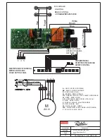
markings identifying the terminals in your plug, proceed as follows.

- The wire which is coloured green and yellow must be connected to the terminal in the plug which is

marked with the letter 

or by the earth symbol or coloured green or green and yellow.

- The wire which is coloured blue must be connected to the terminal which is marked with the letter 

or

coloured black.

- The wire which is coloured brown must be connected to the terminal which is marked with the letter 

or

coloured red.

ATTENTION: Do not forget to use adequate plugs to the support brackets. Enquire after the manu-

facturers. Do an embedding if necessary. The manufacturer accepts no responsibility in case of a 

faulty hanging due to the drilling and the setting up of plugs.

GB

1) Unpack the hood parcel (

A4 & A5

). To remove the cap of the lower chimney and to disconnect the

control.

• LAYING OUT BEFORE FITTING THE HOOD

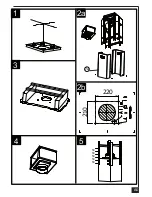
2) Mark the centre of the cooking appliance onto the ceiling with a plumb line. Draw the horizontal axes 

running parallel to the stove top onto the ceiling as illustrated 

Fig. 1

.

3) Place the drill gauge centred on the axes aligning the axes  on the drill gauge centrally over these 

axes as illustrated 

Fig. 2b

.

4) Remove the self-tapping screws, which fix the chimney 

item 7

 to the metal frame bracket as illustrated 

in 

Fig. 2a 

and then remove both sides of the upper chimney stacks.

• 

FITTING THE CANOPY BRACKET

5) Mark the positions on the ceiling for :      - The cut-out for the ducting  Ø 150 mm in the extraction 

mode and Ø 200 mm in the remote mode when ducting runs through the ceiling.


                                                - The mains supply cords.


                                                - The 4 fixing holes for Ø 10 mm nuts and bolts.

Drill the different holes with the appropriate masonry bit. When fixing the cooker hood to a plasterboard 

ceiling ensure it is reinforced as illustrated in 

Fig. 3

 and attach using four Ø10mm nuts and bolts; ensuring 

the bolts as sleeved between the plasterboard and the joist supports to prevent the ceiling being damaged 

when the bolts are tightened up.

If the ceiling is concrete, use eight Ø 10 mm steel rawl bolts. Plastic rawl plugs must not be used.

6) Remove the deflector 

Fig. 4

.

7) The height of the cooker hood can be adjusted in 50 mm stages. 650 mm when fitting above an 

electric hotplate and 700 mm when fitting above a gas hotplate. Select the height required using the 

measurements illustrated in 

Fig. 5


& 6

 and fix the metal diffuser to the frame of the chimney brackets 

using the height 5 x 10T hexagonal headed screws. A drawing on the drill gauge defines the positioning 

for the controls.

Attention:  2 persons are necessary to secure this operation.

8) Check the vertical of the chimney.

• DUCTING

The hood is more effective when used in the extraction mode (ducted to the outside). When the cooker 

hood is ducted to the outside, charcoal filters are not required.

The ducting used must be 150 mm (6 INS), rigid circular pipe and must be manufactured from fire retard-

ant material, produced to BS.476 or DIN 4102-B1. Wherever possible utilise rigid circular pipe which has 

a smooth interior, rather than the expanding concertina type ducting.

Maximum length of ducting run:  

-   4 metres with 1 x 90° bend.

-   3 metres with 2 x 90° bends. 

-   2 metres with 3 x 90° bends.

The above assumes our 150 mm (6 INS) ducting is being installed. Please note ducting components and 

ducting kits are optional accessories and have to be ordered, they are not automatically supplied with the 

chimney hood.

Summary of Contents for Escale 2 centrale 900

Page 1: ...NL Instructions for use and installation Cooker Hood Istruzioni per l uso e l installazione Cappa Instrucciones de instalacion e utilizacion Campana Bedienungsanleitung und Einrichtung Dunstabzugshaub...

Page 2: ...TALACION DEL APARATO FUNCIONAMIENTO CONSEJOS DE UTILIZACION MANTENIMIENTO GARANTIA Y ASSISTENCIA TECNICA NOTA GB CONTENTS ELECTRICAL WIRING INSTALLATION ADVICE FITTING THE APPLIANCE OPERATION USEFUL H...

Page 3: ...cas tre raccord e un conduit de ventilation m canique contr l e V M C Lorsqu on vacue l air vici dans un conduit d vacuation veiller ce que celui ci ne soit pas d j exploit v hiculer des gaz ou fum es...

Page 4: ...e clapet anti retour C sur la sortie de l appareil Rep 6 et raccorder le tuyau flexible l vacuation ext rieure et la sortie de l appareil Fixer l ensemble l aide de colliers ou de ruban adh sif approp...

Page 5: ...s qu moteur teint Affiche 24 et le point en bas droite cli gnote tandis que le moteur est en service Une fois la proc dure termin e la signalisa tion visualis e en pr c dence s teint FF signale la n c...

Page 6: ...rver les prescriptions r glementaires locales concernant l vacuation de l air vici clairage Avant toute intervention sur l appareil mettre l interrupteur d allumage des lampes en position teinte Ne pa...

Page 7: ...riques et lectroniques Veuillez agir selon les r gles locales et ne pas jeter vos produits usag s avec les d chets domestiques usuels Jeter correctement votre produit usag aidera pr venir les cons que...

Page 8: ...are fitted ensure that there is an adequate supply of fresh air to the room Ensure the kitchen is fitted with an airbrick which should have a cross sectional measurement equivalent to the diameter of...

Page 9: ...g holes for 10 mm nuts and bolts Drill the different holes with the appropriate masonry bit When fixing the cooker hood to a plasterboard ceiling ensure it is reinforced as illustrated in Fig 3 and at...

Page 10: ...ot R onto the chimney bracket using the same fixing screws Fig 6a b Connect the ducting 150mm 6 INS not provided between motors item 6 and the recirculation spigot and secure the connections with appr...

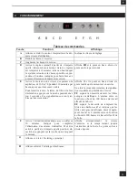
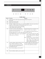
Page 11: ...ions are only visible when the motor is turned off Displays 24 and the bottom right hand spot flashes while the motor is turned on On completing the procedure the previous indicator is turned off FF i...

Page 12: ...th or more frequently if the hood is used for more than 3 hours per day To remove and replace the metal grease filters Remove the metal grease filters one at a time by releasing the catches on the fil...

Page 13: ...on improper use or neglect the replacement of any light bulbs or filters or removable parts of glass or plastic These items are considered to be consumable under the terms of this guarantee 8 REMARKS...

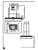
Page 14: ...A1 1000 700 38 mini maxi 979 779 450 164 65 56 22 311 220 210 250 350 350 329 150 35 440 mini 650...

Page 15: ...Connection Unit to BS 1363 Part 4 fitted with a 3 Amp fuse is a recommendedmains supply connectionaccessoryto ensure compliance with the Safety Requirements applicable to fixed wiring instructions The...

Page 16: ...HITE PINK BLANC ROSE WEISS ROSA Y YELLOW JAUNE GELB 110914 PRESTIGE Centrale 1000 depuis Septembre 2011 From 3S_Prestige_C_100_V2011 09 Red White Brown Blue M N L1 F Blue Brown M 230 W L2 L2 e l p r u...

Page 17: ...A4 5 6 Composants Components Bauelemente Componenti Componentes Onderdelen R 7 8...

Page 18: ...A5 Colis Hotte Hood Parcel 1 2 4 3...

Page 19: ...A6 2a 7a 1 3 4 5 2b 220 210 50 50 50 50 50...

Page 20: ...A7 6a 6b 6c 7a...

Page 21: ...A8 7b 6c 2 1 2 3 2 2 1 3 2...

Page 22: ...A9 A 6d C 6 7...

Page 23: ...A10 8 9 7b 2 1 2 3 2 2 1 3 2...

Page 24: ...A11 10 11...

Page 25: ...A12 13MC092 323 x 262 x 9 mm 12 2 LR03 AAA 1 5V 1 3 ACCESSOIRES ACCESSORI ACCESSORIES ACCESORIA ZUBEH RE ACCESSOIRES GU10 28 W 230 V Code 12EC024...

Page 26: ...A13 Halogen Beleuchtung Halogen Lighting Eclairage halog ne Alogene Luci Al genas Luz Halogeen Verlichting 4 x 20 W 12 V 1 2...

Page 27: ...A14 GU10 28 W 230 V Code 12EC024 3 4...

Page 28: ...rie Numero de serie Serienummer Mod le Model Modell Modello Modelo Model Plaque Signal tique de la hotte Rating plate of the cookerhood Typenschild im Inneren der Dunstesse Etichetta all interno della...

Page 29: ......

Page 30: ......

Page 31: ......

Page 32: ...25 Rue des Rosiers Sainte C cile B P 60056 50800 VILLEDIEU LES PO LES France T l 02 33 91 26 50 Fax 02 33 51 54 79 e mail com france roblin fr For outside France Tel 33 0 2 33 91 26 57 Fax 33 0 2 33 5...

Reviews: