background image

SECTION 3: C

RITICAL

 C

ONSIDERATIONS

3

SECTION 3: CRITICAL CONSIDERATIONS
3.1 Basic Information

UHD[X][S][R] heaters have automatic ignition 
burners for ON/OFF operation only.

3.2 Manufactured Units

Gas-fired, power-vented duct furnace with tubular 
heat exchanger. Units shall have a minimum of 82% 
thermal efficiency. The standard unit shall consist of 
a non-separated combustion design with an 
aluminized heat exchanger. Design and heat 
exchanger alternatives shall be offered as follows:

•  Separated Combustion: A separated 

combustion unit shall feature an enclosed, 
sealed burner box. A piece of flexible air duct 
connects this burner box to a flange on the 
cabinet. Combustion air should be ducted from 
outside the heated space, with the ductwork 
connecting to the unit with the use of the flange.

•  Stainless Steel Heat Exchanger: A stainless 

steel heat exchanger unit shall consist of heat 
exchanger tubes, heat exchanger tube supports, 
heat exchanger tube plates and vent box 
produced of 409 stainless steel.

3.3 Location and Suspension

All models:

• Must be installed indoors.

• Must be installed on the positive pressure side of 

the air circulation blower.

• Must be installed in a level position with 

horizontal discharge.

• May be mounted on a shelf of non-combustible 

material.

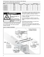
• May be suspended from above (

See Page 8, 

Figure 3

) or from wall brackets of sufficient 

strength to support the heater as listed in the 
Dimension Data Table 

on Page 37, Section 15.1

• Must be installed in a manner which allows 

access to all serviceable components.

See Page 3, Figure 1

 for details.

3.4 Minimum Required Installation Clearances

Clearances around the heater and vent must be as 
indicated 

on Page 3, Figure 1

 and 

Page 11, Figure 4


through Page 14, Figure 9

 to ensure access for 

servicing, and correct operation.

3.5 Clearances to Combustibles

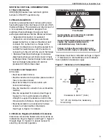
Clearances must be as indicated 

on Page 3, Figure 

1

. If clearances to combustibles are not indicated, 

then installation clearances apply.

Figure 1: Clearances to Combustibles

WARNING

Fire Hazard

Some objects can catch fire or explode 

when placed close to heater.

Keep all flammable objects, li

q

uids and 

vapors the re

q

uired clearances to 

combustibles away from heater.

Failure to follow these instructions can 

result in death, injury or property dama

g

e.

6"

(15 cm)

6"

(15 cm)

31"*

(79 cm)

6"

(15 cm)

Clearance to Vent: 2" (5 cm)

*31" (79 cm) minimum is necessary 
for servicing.

Summary of Contents for Combat 150

Page 1: ...y or property damage Read the Installation Operation and Service Manual thoroughly before installing or servicing this equipment Installer Please take the time to read and understand these instructions prior to any installation Installer must give a copy of this manual to the owner Owner Keep this manual in a safe place in order to provide your serviceman with necessary information Roberts Gordon ...

Page 2: ......

Page 3: ...CTION 7 Air Supply 15 7 1 Separated Combustion Installation 15 7 2 Unvented Installation 15 7 3 Building Ventilation 15 7 4 Outside Combustion Air Supply 15 SECTION 8 Gas Piping 16 8 1 Connections 16 SECTION 9 Wiring 17 9 1 Positioning Thermostats 17 9 2 Low Voltage Thermostat with One Heater 17 9 3 Internal Wiring Diagram 18 9 4 Ladder Wiring Diagram 19 9 5 Electrical Connection to the Heater 20 ...

Page 4: ......

Page 5: ...ination 12 Figure 6 Standard Vented Heater Common Vertical Vent Termination 12 Figure 7 Separated Combustion Heater Vertical and Horizontal Vent Termination 13 Figure 8 Concentric Vent Box 13 Figure 9 Concentric Vertical and Horizontal Vent Termination Separated Combustion Heater 14 Figure 10 Gas Connection 16 Figure 11 Automatic Burner Control Sequence 22 Figure 12 Gas Valve 22 Figure 13 LED Diag...

Page 6: ......

Page 7: ...ot approved for residential installation These instructions the layout drawing local codes and ordinances and applicable standards that apply to gas piping electrical wiring venting etc must be thoroughly understood before proceeding with the installation Protective gear is to be worn during installation operation and service Thin sheet metal parts including the various venting components have sha...

Page 8: ...x the tag by peeling off the backing of the adhesive strips on the rear surface and position the tag on a wall near the heater A copy of the wall tag P N 91039831 is illustrated on the back cover Know your model number Model number is found on the heater and throughout the Installation Operation and Service Manual 2 2 Corrosive Chemicals Caution Do not use heater in an area containing corrosive ch...

Page 9: ...lled on the positive pressure side of the air circulation blower Must be installed in a level position with horizontal discharge May be mounted on a shelf of non combustible material May be suspended from above See Page 8 Figure 3 or from wall brackets of sufficient strength to support the heater as listed in the Dimension Data Table on Page 37 Section 15 1 Must be installed in a manner which allo...

Page 10: ...o allow for proper location of the vent Each heater must be fitted with a correctly sized sealed vent system If vented horizontally no other appliance may be connected to the vent See Page 9 Section 6 WARNING Carbon Monoxide Hazard Heaters may be installed vented or unvented Vented heaters must be vented outdoors Unvented heaters must be installed in buildings with ventilation rates as per section...

Page 11: ...be subject to injury by aircraft cranes movable scaffolding or other objects Provisions shall be made to assure accessibility to suspended heaters for recurrent maintenance purposes 4 3 Parking Structures and Repair Garages Installation in garages must be in accordance with the following codes United States Standard for Parking Structures NFPA 88A latest revision or the Code for Motor Fuel Dispens...

Page 12: ...anada CSA approved heaters installed above 2000 610 m must be de rated For installations above 2000 610 m in US consult factory for information on burner de rating For installations from 2000 610 m to 4500 1370m in Canada high altitude conversion kits are available Heaters installed over 4500 1370 m in Canada are not CSA approved and must be approved by the local or provincial authority ...

Page 13: ...7 Section 5 1 2 Figure 2 Air Flow Direction 5 1 1 Minimum Inlet Duct Length 5 1 2 Temperature Rise and Pressure Drop Ranges Model Duct Length Duct Size W X H UHD X S R 150 175 52 132 cm 28 x 24 71 cm x 60 cm UHD X S R 200 250 60 162 cm 28 x 32 1 4 71 cm x 103 cm UHD X S R 300 400 75 190 cm 28 x 40 1 2 71 cm x 82 cm UHD X S R 150 UHD X S R 175 UHD X S R 200 UHD X S R 225 Airflow CFM Temperature Ris...

Page 14: ...stibles as indicated on the wall tag and in this manual Figure 3 Suspension Methods Model Rate Air Flow Temperature Rise Btu h Minimum CFM Maximum CFM Minimum F Maximum F UHD X S R 150 150 000 1 360 5 800 20 83 UHD X S R 175 175 000 1 400 6 850 20 95 UHD X S R 200 200 000 2 050 7 750 20 73 UHD X S R 225 225 000 2 100 8 300 20 80 UHD X S R 250 250 000 2 350 8 850 22 80 UHD X S R 300 300 000 2 700 1...

Page 15: ... terminate at least 3 9 m above any forced air inlet located within 10 3 1 m Vent must terminate at least 4 1 2 m below 4 1 2 m horizontally from or 1 3 m above any door operable window or gravity air inlet into any building NFPA 54 ANSI Z223 1 latest revision National Fuel Gas Code specifies a 4 1 2 m horizontal vent terminal clearance from gas and electric meters regulators and relief equipment ...

Page 16: ...e harm 6 5 Horizontal Venting Horizontally vented heaters must be individually vented Vent pipe must be sloped 6 cm downward for every 1 3 m For vent lengths greater than 5 1 5 m condensation will form Insulation is recommended and condensation drains may be desired In noncombustible walls only vent terminal P N 02537801 1P may be used For 4 10 cm vents in either combustible or noncombustible wall...

Page 17: ...ndows and all doors between the space in which the appliance s connected to the venting system are located and other spaces of the building Turn on clothes dryers and any exhaust fans such as range hoods and bathroom exhausts so that they shall operate at maximum speed Do not operate a summer exhaust fan Close fireplace dampers 4 Follow the lighting instructions Place the appliance being inspected...

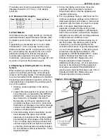
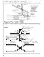
Page 18: ...ON OPERATION AND SERVICE MANUAL 12 Figure 5 Standard Vented Heater Vertical and Horizontal Vent Termination Figure 6 Standard Vented Heater Common Vertical Vent Termination Model Vent Diameter Part Number UHD X R 150 400 4 10 cm 90502102 ...

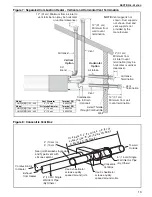
Page 19: ...not shown Duct supports not shown Duct and vent supports not provided by the manufacturer 12 31 cm Minimum from wall to vent termination Model Vent Diameter Terminal P N UHD X S R 150 400 4 10 cm 90502102 Model Air Intake Diameter Terminal P N UHD X S R 150 250 4 10 cm 90502102 UHD X S R 300 400 5 13 cm 90502105 4 10 cm Single Wall Vent Pipe By Others Seal joint between single wall and Type B vent...

Page 20: ...lf Drilling 91119100 14 4 10 cm Vent Terminal with Baffle Plate 90502102R 1 6 15 cm Combustion Air Terminal 90502103 1 Description Part Number Qty Concentric Vent Kit 300 400 UHVK2 Concentric Vent Box Top Side Assembly 90504013 1 Concentric Vent Box Bottom Assembly 90504012 1 Screw 6 x 3 8 Self Drilling 91119100 14 4 10 cm Vent Terminal with Baffle Plate 90502102R 1 8 20 cm Combustion Air Terminal...

Page 21: ...entilation Where ventilation is required air must be taken from an outside point where it is not likely to be contaminated or obstructed 7 4 Outside Combustion Air Supply If outside combustion air supply is required separated combustion model UHD X S R heaters must be used Caution If the building has a slight negative pressure or corrosive contaminants such as halogenated hydrocarbons are present ...

Page 22: ... 1 8 NPT plugged tapping accessible for test connection must be installed immediately upstream of the gas supply connection to the heater For suspended heaters an approved metal flexible connection between the isolating valve and the heater may be used To reduce pressure loss use one pipe size larger than the heater gas connection IMPORTANT The complete installation must be purged and tested for g...

Page 23: ...Electrical Code CSA C22 1 Part I latest revision 9 1 Positioning Thermostats A room thermostat should be mounted on a vibration free wall or column at a height of approximately 5 1 5 m from the floor to measure the ambient temperature It should be clear of both cold drafts and the direct path of warm air from the heater Avoid mounting thermostat on outside walls or in areas directly exposed to rad...

Page 24: ...arger wires BLUE BLACK ORANGE ORANGE YELLOW BROWN WHITE WHITE L2 L1 ORANGE ORANGE BLACK BLACK GREEN WHITE BLUE BLACK GREEN BLUE GREEN YELLOW 24 VAC HOT GROUND FLAME BLACK BLACK 6 3 4 2 1 4 5 3 1 SENSE ELECTRODE LIMIT SWITCH PRESSURE SWITCH GAS VALVE IGNITION MODULE TRANSFORMER LIMIT SWITCH UHD 300 350 400 ONLY MANUAL RESET LIMIT SWITCH RESIDENTAL UNITS ONLY THERMOSTAT INPUT FIELD SUPPLIED R 24 VAC...

Page 25: ...placed with wiring material having a temperature rating of at least 105 C 221 F and 600 V For supply connections use No 14 AWG or larger wires FLAME SENSOR PRESSURE SWITCH THERMOSTAT CONNECTION 6 3 4 5 2 1 120 VAC TRANSFORMER FLUE BLOWER GAS VALVE ELECTRODE IGNITION MODULE FLAME SPARK LIMIT SWITCH LIMIT SWITCH UHD 300 350 400 ONLY MANUAL RESET LIMIT SWITCH UHD 75 125 ONLY FLUE BLOWER ...

Page 26: ... Junction box is not provided with heater Conduit can also be attached directly to heater with wire junction made within the heater cabinet BX Connector Junction Box Flexible Conduit Burner Connect wires together with suitable approved wire connectors Green to Ground White to L2 Black to L1 L1 L2 Ground Black White Green ...

Page 27: ...ged from the heater inlet pipe up to the main gas valve inlet test nipple 10 1 3 Mechanical Checks 1 Check that the flue and air intake for separated combustion units is installed in accordance with these instructions and local regulations 10 2 Begin Start Up 10 2 1 Before Operating the Heater To ensure that all the controls are in safe working order operate the heater for the first time with the ...

Page 28: ...coming Signals Flue Blower Pressure Switch P C NO NC 30 Seconds Purge Purge time begins at pressure switch change over 30 Seconds Post Purge If at any stage the flame fails the control will retry for ignition The control has four trials for ignition before a one hour lockout PSI IN C ON OFF Regulator Outlet Pressure Gas Inlet Inlet Pressure TOP VIEW END VIEW Description Part Number Gas Valve 150 2...

Page 29: ...5 minutes and then re check settings Adjust pressure setting if necessary 2 Check gas flow rate at gas meter 3 Turn off heater and electrical supply 4 Remove the manometer and refit all covers to the valve and tighten the screw of the outlet pressure tap 10 2 3 Pressure Switch The pressure switch is factory pre set for each model and is not adjustable 10 2 4 Turning Off the Heater Set the thermost...

Page 30: ...ated This may be caused by an interruption of the electrical supply failure of the distribution fan or vent or heat exchanger blockage If a temperature limit switch persistently trips there is a fault which must be investigated by a contractor qualified in the installation and service of gas fired heating equipment 11 4 1 Simple Troubleshooting Burner Faults If the burner fails to ignite for any r...

Page 31: ...an unless a problem has developed with combustion Inspect the heat exchanger Look for signs of overheating at the front tubes which may indicate burner over firing or persistently low air flows 12 4 Gas Valve Maintenance No regular maintenance is required on this device To change gas control valves See Page 32 Section 14 1 Do not repair or disassemble gas valve Replace faulty gas valves with repla...

Page 32: ... follow these instructions can result in death injury or property damage The Vicinity of the Heater Do not store or use flammable objects liquids or vapors near the heater Immediately remove these items if they are present See Page 3 Section 3 Vehicles and Other Objects Maintain the clearances to combustibles Do not hang anything from or place anything on the heater Make sure nothing is lodged in ...

Page 33: ... 17 Section 9 Suspension Points Make sure the heater is hanging securely Look for signs of wear on the suspension materials or ceiling See Page 8 Figure 3 Silicone Tubing Ensure tight secure fit on all pressure fittings at pressure switch burner partition and blower outlet Gas Valve Verify that cap covering pressure regulator adjustment screw is secure and has not been tampered with Verify all wir...

Page 34: ...cle No Yes Does the flue blower run No Use Troubleshooting for Flue Blower section to test fan Yes Yes Burner has locked out due to ignition failure Use Troubleshooting for Automatic Ignition Burner Systems section to test burner Is ignition control showing a 2 flashes LED code Yes No Yes START Yes Wait 10 15 minutes for limit switch to cool Does fan stop running No Turn on supplies Are gas electr...

Page 35: ...y or wiring connections faulty Repair or replace as required Check for too much vent air inlet duct Check for blockage in vent and combustion air circuit Check for faulty air pressure switch Check pressure switch hoses for leaks or cracks Do not attempt to circumvent pressure switch circuit to place unit in operation See Pressure Switch section for details Does air pressure switch change over No Y...

Page 36: ...www rg inc com Replace ignition control Use General Troubleshooting section to trace the fault Heater Operating TROUBLESHOOT ENDS No Repair or replace as required Is inlet burner gas pressure correct Is live and neutral polarity correct Is flame probe circuit correct Is there a current flowing in the flame probe circuit with no flame present Yes No Does lockout occur when there is a flame present ...

Page 37: ...outlet of the valve rise when valve turns on No Yes Is gas pressure at inlet of the valve correct for gas type Note pressure found No Yes START For optimum heater performance use only replacement parts sold and supplied by Roberts Gordon Conduct start up procedure as shown on Page 21 Section 10 If problems persist contact Roberts Gordon LLC at www rg inc com Blower Operating TROUBLESHOOT ENDS No B...

Page 38: ...oint Check that all the joints are leak free Reset gas valve See Page 23 Section 10 2 2 IT IS IMPORTANT THAT ONLY THE CORRECT GAS VALVE IS USED WHEN REPLACING THESE CONTROLS WARNING Explosion Hazard Installation service and annual inspection must be done by a contractor qualified in the installation and service of gas fired heating equipment or your gas supplier Turn off gas and electrical supplie...

Page 39: ...1930053 Remove flexible air duct from spigot Remove access plate Remove screws and pull off burner compartment cover Viewing port for flame probe Viewing port for ignition electrode Flame Probe Burner Compartment Cover Rubber Seal Ignition Electrode The burner compartment is a sealed compartment Following any work re seal the compartment with the gas pipe rubber seal fully in place and all screws ...

Page 40: ...Inshot Burners UHD X S R 200 92000000 9 Inshot Burners UHD X S R 225 92000000 10 Inshot Burners UHD X S R 250 92000000 11 Inshot Burners UHD X S R 300 92000000 12 Inshot Burners UHD X S R 350 92000000 14 Inshot Burners UHD X S R 400 92000002 14 Limit Switch 150 400 90412103 1 Limit Switch 300 400 90412105 1 Limit Switch 175 90412107 1 To replace the electrode or flame probe remove the electrical l...

Page 41: ...PECIFIED FOR EACH MODEL TYPE IS USED WHEN REPLACING THESE ITEMS Carry out a start up after working on or changing a flue blower See Page 24 Section 11 MODEL UHD X S R 150 175 UHD X S R 200 300 UHD X S R 350 400 Flue Blower P N 90710405 90710403 90710402 Remove screws securing outlet flange to the flue adapter Refit in reverse order Remove screws securing flue blower mounting plate to vent box Remo...

Page 42: ... noting their positions Release the four mounting standoffs Refit in reverse Ensure correct location of ignition cable and all other wiring 14 8 Limit Switches 14 8 1 Removal and Replacement 1 Remove the electrical connections to the switch 2 Unscrew the two screws securing the switch 3 Fit a new switch with two screws 4 Reconnect the electrical connections and test operation MODEL UHD X S R 150 1...

Page 43: ... 25 3 1 25 3 1 25 3 1 25 3 1 25 3 1 25 3 1 25 3 1 25 3 D Support Spacing in cm 12 3 31 12 3 31 12 3 31 12 3 31 12 3 31 12 3 31 12 3 31 12 3 31 E Support Spacing in cm 12 4 32 12 4 32 12 4 32 12 4 32 12 4 32 15 3 39 15 3 39 15 3 39 F Support Spacing in cm 17 7 45 17 7 45 17 7 45 17 7 45 17 7 45 24 7 63 124 7 63 24 7 63 G Center of Flue in cm 15 5 39 15 5 39 17 5 44 17 5 44 17 5 44 13 8 35 13 8 35 1...

Page 44: ... Air Volume CFM 5800 6850 7750 8300 8850 10200 13600 14200 Temperature Rise Maximum Air Volume F C 20 7 20 7 20 7 20 7 22 6 23 5 22 6 22 6 Heat Exchanger Pressure Drop Maximum Air Volume in wc 0 16 0 29 0 163 0 253 0 35 0 27 0 48 0 53 Flue Size in cm 4 All Models 10 Air Intake in cm 4 10 4 10 4 10 4 10 4 10 5 13 5 13 5 13 Model UHD X S R 150 UHD X S R 175 UHD X S R 200 UHD X S R 225 UHD X S R 250 ...

Page 45: ...t You cannot prove original purchase date and required annual maintenance history The data plate and or serial number are removed defaced modified or altered in any way The ownership of the ROBERTS GORDON COMBAT UHD Series is moved or transferred This warranty is nontransferable Roberts Gordon is not permitted to inspect the damaged controller and or component parts READ YOUR INSTALLATION OPERATIO...

Page 46: ......

Page 47: ...Type of Installation check one o Automotive o Manufacturing o Warehouse o Recreational o Aircraft o Public Building o Office o Retail o Agricultural o Other______________ Mail or Fax to Roberts Gordon LLC 1250 William Street P O Box 44 Buffalo NY 14240 0044 Phone 716 852 4400 Fax 716 852 0854 Toll Free 800 828 7450 www rg inc com Installation Code and Annual Inspections All installations and servic...

Page 48: ......

Page 49: ......

Page 50: ... property damage TO TURN OFF THE HEATER Roberts Gordon LLC 1250 William Street P O Box 44 Buffalo NY 14240 0044 USA Left Right Bottom Top Clearances to Combustibles Installation Code and Annual Inspections All installation and service of ROBERTS GORDON equipment must be performed by a contractor qualified in the installation and service of equipment sold and supplied by Roberts Gordon and conform t...

Reviews: