background image

3

Club

Spot

500

CT

Table of contents

1. Safety instructions..................................................................................................................... 4

2. Operating determinations......................................................................................................... 4

3. Description of the device.......................................................................................................... 5

4. Installation.................................................................................................................................. 6

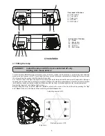
4.1 Fitting the lamp........................................................................................................................... 6
4.2 Lamp adjustment........................................................................................................................ 7
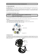
4.3 Inserting / Exchanging  gobos.................................................................................................. 7
4.4 Manual zoom............................................................................................................................... 7
4.5 Connection to the mains............................................................................................................ 8
4.6 Changing the power supply settings ........................................................................................8
4.7 Rigging the fixture...................................................................................................................... 9
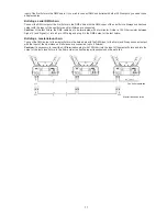
4.8 DMX-512 connection/connection between fixtures ...............................................................10

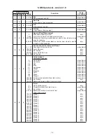
5. DMX protocol - version 1.0...................................................................................................... 12

6. Controller mode .......................................................................................................................14

6.1 DMX addressing ........................................................................................................................14
6.2 Remotely controllable functions............................................................................................. 14

7. Stand - alone mode.................................................................................................................. 15

8. Control menu map.................................................................................................................... 16

9. Control menu............................................................................................................................18

9.1 Fixture Address ........................................................................................................................18
9.2 Slave control ...........................................................................................................................18
9.3 Fixture informations ................................................................................................................18
9.4 Personality ............................................................................................................................19
9.5 Lamp On/Off............................................................................................................................. 20
9.6 Test sequences ........................................................................................................................20
9.7 Stand-alone setting ................................................................................................................. 20
9.8 Reset functions ........................................................................................................................21
9.9 Special functions .....................................................................................................................21

10. Error and information messages.......................................................................................... 21

11. Technical specifications........................................................................................................ 22

12. Maintenance and cleaning..................................................................................................... 25

Summary of Contents for clubspot 500 CT

Page 1: ...Version 1 1 ...

Page 2: ......

Page 3: ... 8 DMX 512 connection connection between fixtures 10 5 DMX protocol version 1 0 12 6 Controller mode 14 6 1 DMX addressing 14 6 2 Remotely controllable functions 14 7 Stand alone mode 15 8 Control menu map 16 9 Control menu 18 9 1 Fixture Address 18 9 2 Slave control 18 9 3 Fixture informations 18 9 4 Personality 19 9 5 Lamp On Off 20 9 6 Test sequences 20 9 7 Stand alone setting 20 9 8 Reset func...

Page 4: ...you connect the device to the mains The power plug has to be accessable after installing the device Make sure that the power cord is never crimped or damaged by sharp edges Check the device and the power cord from time to time Always disconnect from the mains when the device is not in use or before cleaning it Only handle the power cord by the plug Never pull out the plug by tugging the power cord...

Page 5: ...scharge lamps may explose and emit a high ultraviolet radiation which may cause burns The maximum ambient temperature 40 C must never be exceeded Otherwise the lamp is switched off and the fixture is out of operation for 5 minutes CAUTION The lens has to be replaced when it is obviously damaged so that its function is impaired e g due to cracks or deep scratches Operate the device only after havin...

Page 6: ...d for Damages caused by non observance are not subject to warranty Please follow the lamp manufacturer s notes Do not touch the glass bulb with bare hands during the installation Make sure that the lamp is installed tightly into the lampholder system Reclose the lamp cover and tighten the 3 screws Before striking the lamp reset the LAti and LASt counter s in the menu of the Control Board by pressi...

Page 7: ...allow it to cool for at least 10 minutes Disconnect the fixture from power Open the top cover of the moving head by loosening the 2 quarter turn fasteners on the top cover and follow the instruc tions below 1 Use an appropriate tool e g screwdriver with narrow tip to pull out the spring gobo lock 2 Caution remove the gobo and supporting ring from gobo holder 3 Insert the supporting ring and the ne...

Page 8: ... 6 Changing the power supply settings Both the transformer and the ballast must be connected correctly for the local AC voltage and frequency The wrong settings can cause poor performance or demage of the moving head The factory settings are printed next to the power switch If you want to change the power supply settings follow the instructions 1 Disconnect the fixture from AC power 2 Remove the t...

Page 9: ...ved by an expert after every four year in the course of an acceptance test The operator has to make sure that safety relating and machine technical installations are approved by a skilled person once a year The projector should be installed outside areas where persons may walk by or be seated IMPORTANT OVERHEAD RIGGING REQUIRES EXTENSIVE EXPERIENCE including but not limited to calculating working ...

Page 10: ...e omega holders 1 Bolt each clamp 1 to the omega holder 4 with M12 bolt and lock nut through the hole in the holder 2 Fasten the omega holders on the bottom of the base by inserting both quick lock fasteners 3 into the holes of the base and tighten fully clockwise 3 Fasten the safety rope 2 through the two apertures on the bottom of the base and over the trussing system 1 Shield 2 Signal 3 Signal ...

Page 11: ...terminator Solder a 120 Ohm resistor between Signal and Signal into a 3 pin XLR plug and plug it in the DMX output of the last fixture Building a master slave chain Connect the DMX output of the master fixture in the data chain with the DMX input of the first slave Always connect output with the input of the next slave until all slaves are connected up to 9 fixtures Caution It s necessary to inser...

Page 12: ... step step step step 7 7 5 0 13 26 38 51 64 77 90 102 115 128 189 190 193 194 255 Colour wheel 1 Continual Positioning Open white Light blue Red Blue Light green Yellow Magenta Cyan Green Orange Forwards rainbow effect from fast to slow No rotation Backwards rainbow effect from slow to fast proportional proportional proportional proportional proportional proportional proportional proportional prop...

Page 13: ...ation from fast to slow No rotation Backwards gobo rotation from slow to fast proportional proportional step proportional 11 11 9 0 255 Focus Continuous adjustment from far to near proportional 12 12 10 0 31 32 63 64 95 96 127 128 143 144 159 160 191 192 223 224 255 Shutter strobe Shutter closed Shutter open Strobe effect from slow to fast Shutter open Closing pulses from slow to fast Opening puls...

Page 14: ...llable functions Lamp The ClubSpot 500 CT is to be operated with a Philips MSR 575 2 or Osram HSR 575 2 A relay inside of the ClubSpot 500 CT allows you to switch on and off the lamp via the control panel or via your DMX controller without affecting the rest of the lighting To switch On Off the lamp please refer to Switching On Off the lamp menu LAMP Note It is also important to note that the disc...

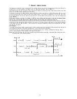
Page 15: ...s will execute these acts too e g if the master fixture has switched the lamp off no slave can switch the lamp on The master fixture starts simultaneous program start in the other slave fixtures All fixtures have a definite synchronized starting point when playing back their programs The number of running program is the same in all slaves and depends on the master s choice menu St AL Every fixture...

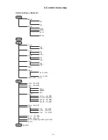
Page 16: ... totl rSEt LA St totl rSEt Hi tE totl rSEt tEMP DM ln Pan 0 255 dim 0 255 VErS ICI b ICIr PErS r PAn On Off r tilt On Off 16b r Mod 1 Mod 2 8bit La Pr LA Au On Off d L O F On Off dM On On Off dM OF On Off En Sn On Off dISP turn On Off d On On Off d lnt 20 100 bL Co On Off FEEd On Off FAn S Auto High rEG LoOF LoHi dF SE LAMP On Off ...

Page 17: ...1 PrG 2 PrG 3 PLAY tESt PrG 1 PrG 2 PrG 3 Edit PrG 1 PrG 2 PrG 3 St 01 St 99 PAn 0 255 S tim 0 1 25 5 s rESE COPY SPEC MAnu PAn Pan 1 Pan 3 dimr dim 0 dim C LA Ad PAn 0 255 tilt 0 255 Foc 0 255 CodE AdJ PAn F CAL Colo 0 255 dimr 0 255 A rES UPd M ...

Page 18: ...ber of the operation hours since the ClubSpot 500 CT has been fabricated rSEt The function shows the number of the operation hours that the ClubSpot 500 CT has been powered on since the counter was last reset In order to reset this counter to 0 you have to hold UP and DOWN and press the ENTER La ti Lamp on time Select this submenu to read the number of the operation hours with the lamp on totL The...

Page 19: ...damaged or absent on this account some electronics parts could be damaged diSP Display adjusting This function allows you to change the display settings turn Select this function to turn the display by 180 d On This function allows you to keep the display on or to turn off automatically 2 minutes after last pressing any button on the control panel d Int Select this function to adjust the display i...

Page 20: ...created program No 1 PrG 2 The option starts created program No 2 PrG 2 The option starts created program No 3 Select the program you wish and press ENTER The selected program starts running By Pressing ENTER again is possible to pause the program running Edit Editing program Select this menu to edit or create the program The ClubSpot 500 CT has one built in program and the 3 free programs each up...

Page 21: ...ck the newly adjusted positions of the colour gobo wheels and dimmer When the reset of the fixture is finished the display will show the F CAL message Press ENTER to repeat the calibration or MODE to return to the AdJ menu 2 Calibration via the external controller Connect the DMX controller to the fixture press ENTER and the UP and DOWN buttons in order to display the fol lowing items Colo r Gob G...

Page 22: ...This message can appear as a result of the interference during the lamp starting if the lamp or igniter is old or as a result of the interference by neighbouring devices In these cases the message does not affect the fixture operating Sn Er This message appears if the lamp lighting sensor is failed PoEr This message will appear if the fixture was shortly disconnect from the main PA Er Pan movement...

Page 23: ...out fixture and lamp usage receiving DMX values temperature etc Built in analyzer for easy fault finding error messages Remotely switching of the lamp Bilt in demo sequences Silent fans cooling remotely controllable speed of fans Self resetable thermo fuse Stand alone operation Master slave operation Digital serial input DMX 512 3 DMX protocol modes 11 or13 control channels Pan Tilt Pan movement r...

Page 24: ...24 Beampath Dimensions mm Weight net EU version 31 7 kg US version 35 6 kg ...

Page 25: ...ly The gobos may be cleaned with a soft brush The interior of the fixture should be cleaned at least annually using a vacu um cleaner or an air jet The dichroic colour filters the gobo wheel and the internal lenses should be cleaned monthly There are no serviceable parts inside the device except for the lamp and the fuse Please refer to the instructions under Fitting Exchanging the lamp Maintenanc...

Page 26: ...26 ...

Reviews: