


Lynx™ Embedded Sensors LES‑B‑127‑50/125/500/2000 | Product Manual
4
OPERATION
BUTTON‑STYLE/UNDER‑PIN
The Lynx single‑channel, button‑style strain
gage sensor is placed in a mold behind
an ejector pin. As plastic is injected into
the cavity, the pressure of the plastic
applies force to the ejector pin; the plastic
pressure force is transfered to the strain
gage sensor.
STRAIN GAGE SENSORS
The strain gage sensing element inside the
sensor body converts the applied force to
an electrical signal that can read using the
eDART system or CoPilot system software.
The sensing element uses a Wheatstone
bridge configuration (four strain gage
elements positioned in a circuit) to convert
small amounts of sensor deformation into
a measurable voltage through the change
in resistance of the strain gage sensing
elements. The sensor sends out a low‑level
voltage signal which is proportional to the
amount of force applied by the pressure
placed on the pin and transferred to the
sensor.
The voltage measurement is carried
through the sensor cable, to the Lynx
sensor electronics case mounted inside the
mold. The voltage signal is converted by
the sensor’s electronics to a high‑accuracy
digital output that directly correlates with
pressure from within the cavity.
The sensor are connected to the RJG, Inc.
eDART System, which records and displays
the sensor’s measurement for use in
process monitoring and control. In addition,
the sensor electronics communicates the
sensor model, serial number, full scale
load, and calibration data automatically to
the eDART or CoPilot system, providing
the highest level of sensor accuracy while
minimizing the need for user‑entered data
when configuring the sensor in the eDART
or CoPilot systems.
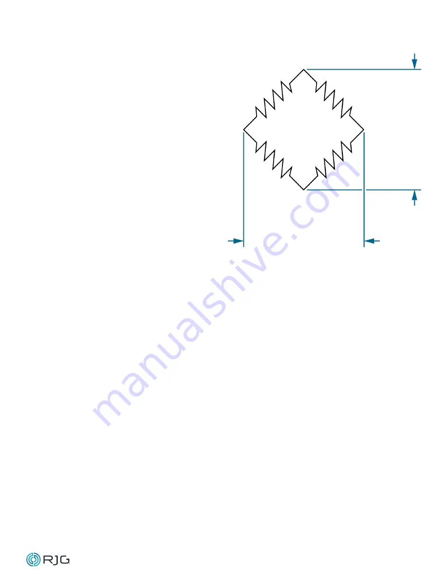
EXCITATION
Gate 1
Gate 2
Gate 3
Gate 4
OUTPUT
STRAIN GAGE OPERATING PRINCIPLE


