background image

Check for parts online at 

www.huntriversedge.com

 or call 800-450-EDGE (3343) M-F 8-5

Check for parts online at 

www.huntriversedge.com

 or call 800-450-EDGE (3343) M-F 8-5

16

Operator's Manual

Rivers Edge One-Man Ladder Stands

ASSEMBlY INSTRuCTIONS (RE607)

Tools needed – two 7/16" wrenches 
iMpoRtant aSSEMblY tip:  do not tighten any nut and bolt combinations 

completely until all parts are assembled together! Finger tighten plus one 

turn of a wrench only! this will temporarily hold the lock nut on the bolt while 

helping alignment of all parts! after all parts are assembled together, all nut 

& bolt combinations must be completely tightened.

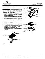
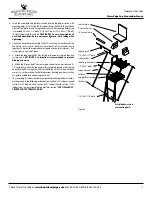
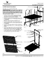
1.  Attach the foot platform (48045) to the inside of side rails (1ML24) using (2) 

provided 1/4-20 x 2-1/4” bolts and locknuts. SEE fIGuRE 1.  DO NOT tighten 

all nut & bolt assemblies completely!


notE: Mesh surface should be on top with squared ends of platform 

closest to side rails.

2.  Attach the tree blade frame (1ML34) to the inside of side rails, and the (2) shooting 

rail mounts (112ML43) and (2) armrests (LFX5) to the outside of side rails using 

(4) provided 1/4-20 x 3-1/4" bolts, locknuts and steel washers. SEE fIGuRE 2A. 

3.  Attach seat frame (1ML15) to the tabs on the tree blade frame using (2) 

provided 1/4-20 x 1-1/2” bolts, locknuts, nylon washers and (4) steel washers. 

SEE fIGuRE 2B. Attach the (2) provided rubber bumper stops to top side 

of tree blade frame by pressing in to provided holes. SEE fIGuRE 2B.


notE: Mesh surface of seat frame should be on top.


notE: nylon washers should be placed between tabs and seat frame to 

eliminate noise.

Figure 1

cutout view

of foot platform

1/4-20 x 2-1/4”

bolts

locknuts

side rails

Figure 2A

1/4-20 x 3-1/4” bolts

locknuts

steel washers

Figure 2B

locknuts

tree blade frame

seat frame

1/4-20 x 1-1/2” bolts

rubber bumpers

tabs

nylon washers

steel washers

steel washers

tree blade frame

side rails

shooting rail mounts

armrests

Summary of Contents for RE607

Page 1: ...1 2011 RETI All Rights Reserved Get parts online at www HuntRiversEdge com Spin Shot Model RE623 Includes Model s RE619 20 Lumberjack Extreme Ladder RE607 22 Timbershot Extreme Ladder RE623 17 Spin Shot Ladder RE624 15 Opening Day Ladder LumberJack Extrme Model RE619 ...

Page 2: ... its products or due to any use which deviates from the products intended usage The manufacturer also is not responsible for any injuries sustained due to failure to adhere to the instructions for use Any misunderstanding of its operation should be directed to manufacturer prior to its use All Rivers Edge treestands come with a full body harness fall arrest system that meets tma standards It is th...

Page 3: ...BEEN MAIN TAINED OR INSPECTED PROPERLY YOUR LIFE DEPENDS ON IT WHEN HUNTING FROM A TREESTAND FALLS CAN OCCUR ANY TIME AFTER LEAVING THE GROUND CAUSING INJURY OR DEATH NEVER ATTACH TO A DEAD ODD SHAPED LEANING DIS EASED LOOSE BARKED TREE OR UTILITY POLES warning REPLACE ANY AND ALL TREESTAND STRAPS EVERY TWO YEARS OR WHEN ANY SIGNS OF DAMAGE OR WEAR EXIST BEFORE Some models include a footrest which...

Page 4: ...R AND OR DAMAGE NEVER USE A DAMAGED PROD UCT THIS PRODUCT IS DESIGNED FOR ADULT USE ONLY ADULTS MUST BE BETWEEN 120 LBS MINIMUM AND 300 LBS max imum TO USE THIS PRODUCT before attempting to use this harness practice in stalling set up and use at ground level once you become comfortable with its set up and use you may proceed and use it at heights above ground do not use this product or any rivers ...

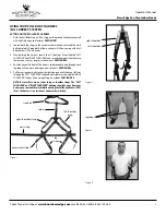
Page 5: ...rt to make sure there are no twists or tangles in the harness SEE FIGURE 2 4 Position yourself in front of the harness and proceed to step through each leg loop as if you were putting on a pair of pants SEE FIGURE 3 5 Pull harness up your body to chest height where you will slide your left arm throughthe LEFTSHOULDER strapandyourrightarmthroughthe RIGHT SHOULDER strap as if you were putting on a j...

Page 6: ...uncomfortably tight SEE FIGURE 6 8 YoushouldnowhavetheFullBodyHarness FAS configuredwiththewaist strap on your front side shoulder straps over the proper shoulders and the tether strap positioned on your back side SEE FIGURES 7 8 The entire Full Body Harness FAS should have a snug tight fit to your body NOTE Tether strap should not be tangled twisted or looped around any portion of the harness Exc...

Page 7: ... tight NOTE Be sure the 2 adjustment slides are facing away from tree preventing any obstruction Do not position tether on or be tween the 2 tree belt adjustment slides SEE FIGURE 9 Once you have reached your desired hunting height you must slide the tree belt up the tree as high as possible Tighten the tree belt to the tree by pulling the tree belt tail tight The tether strap accommodates your fr...

Page 8: ...just the length of the SRD strap to relieve pressure off the leg straps 6 You can also adjust the SRD strap to a shorter length and place your knees on the SRD strap to relieve the pressure from the harness leg straps SEE FIGURE 5 Alternating between the standing method on feet and the kneeling method on knees comfort and better blood circulation are maintained warning THE SUSPENSION RELIEF DEVICE...

Page 9: ...TRAP STORED IN THE STORAGE POUCH SO YOU HAVE ACCESS TO IT THE SUSPENSION RELIEF DEVICE IS DESIGNED FOR PRO VIDING IMMEDIATE RELIEF FROM PROLONGED SUSPEN SION TRAUMA IF YOU ARE NOT PHYSICALLY ABLE TO PER FORM THE STEPS INVOLVED IN THE CORRECT USE OF THIS SUSPENSION RELIEF DEVICE SRD STRAP YOU SHOULD HUNT FROM GROUND LEVEL ONLY Hunters with varying degrees of physical fitness may require different p...

Page 10: ...upon reaching foot platform Be fully aware of foot placement Recommended for adult use only Inspect ladder for missing parts all hardware condition and damage before every application replace if necessary Pull up a bow backpack firearm or other equipment only after being secure in the treestand and a fire arm must be pulled up with it unloaded chamber open and muzzle down Remove ladder after every...

Page 11: ...ndthe 2 armrests AR12 totheoutsideofsiderailsusing 2 provided 1 4 20 x 3 1 4 bolts locknuts and steel washers See figure 2 3 Attach the front end of tree blade frame to the side rails and the front end of armrests to the side rails using 4 provided 1 4 20 x 2 1 4 bolts lock nuts and 2 steel washers See figure 2 4 Attach the seat frame 1ML15 to the tabs on the tree blade frame using 2 provided 1 4 ...

Page 12: ...o the top of seat frame Wrap the Velcro straps or buckle straps around seat frame and secure together Snap the side release buckles together for buckle style seats Pull straps tight so seat is not loose 8 a Attachtheshootingrail SR10 bysettingraildownoverstudsonarmrests SEE FIGURE 4 Lubrication is recommended to prevent binding and noise b Attach the 2 provided 9 camo sleeves to the armrests and t...

Page 13: ...unting bracket using 1 provided spring lock pin SEE FIGURE 6 b Slide the stabilizer bar L17 into the extension tube and attach the two pieces together using 1 provided spring lock pin Spring lock pin must go through both the extension tube and stabilizer bar at appropriate hole to achieve desired distance from tree Adjustment in length may be needed when ladder is uprighted later in instructions S...

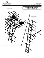
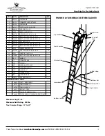
Page 14: ...vers Edge One Man Ladder Stands NO EXTENSIONS AVAILABLE FOR THIS MODEL tESTED FOR 20 MAXIMUM HEIGHT 14 6 11 19 8 10 14 14 11 11 12 16 23 7 5 22 18 2 15 15 21 20 10 ladder PARTS Upper Section ladder PARTS Lower Section 14 6 11 19 8 10 14 17 14 11 10 13 3 25 1 24 14 13 12 10 9 4 14 11 12 16 23 7 5 22 18 2 10 ...

Page 15: ... 14 48752b NUT FLANGED NyLOCK 1 4 20 18 15 63281 SNAP PIN 1 4 X 1 3 4 2 16 67540b BOLT HHCS GR5 BLK 1 4 20 X 2 3 4 2 17 AR12 ARMREST 2 18 l17 STABILIZER BAR 1 19 sl61 SIDE RAIL 2 20 sl71 LADDER BOTTOM 53 1 21 sl72 LADDER W VAM 53 1 22 sl73 LADDER 53 1 23 SL74 LADDER TOP 53 1 24 sr10 SHOOTING RAIL 1 25 wn516 WASHER BLK 5 16 2 ITEMS BELOW NOT SHOWN 48819 SEAT 1 W BACKREST 1 48737 CAMO SLEEVE 18 1 48...

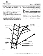
Page 16: ...closest to side rails 2 Attachthetreebladeframe 1ML34 totheinsideofsiderails andthe 2 shooting rail mounts 112ML43 and 2 armrests LFX5 to the outside of side rails using 4 provided1 4 20x3 1 4 bolts locknutsandsteelwashers Seefigure2A 3 Attach seat frame 1ML15 to the tabs on the tree blade frame using 2 provided1 4 20x1 1 2 bolts locknuts nylonwashersand 4 steelwashers See figure 2B Attach the 2 p...

Page 17: ...ing 5 Attach the removable seat cushion 48819 to the top of seat frame Wrap the Velcro seat straps or buckle straps around seat frame and secure together Snap the side release buckles together for buckle style seats Pull straps tight so seat is not loose 6 a Attachtheshootingrail SR10 bysettingraildownoverstudsonshooting rail mounts See figure 3 Lubrication is recommended to prevent binding and no...

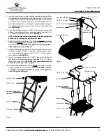
Page 18: ...be needed when ladder is uprighted later in instructions See figure 4 Figure 4 stabilizer bar extension tube spring lock pin third ladder section 1 3 4 wing bolts second ladder section 2 1 2 spring lock pin second ladder section mounting bracket truss support spring lock pin truss support mounting bracket wing nut counter lock support bar 10 Insert the 4 truss male braces 48041 into the 4 truss fe...

Page 19: ...h ladder sections together using 4 provided 1 4 20 x 1 3 4 wing bolts and wing nuts See figure 6 12 Tightenallwingbolt wingnutcombinationssecurelybyhand Besure nottoovertightenorcrushtubing Doubleandtriplecheckallhardware locations to make sure they are all securely fastened 13 Tie one end of each of the provided 22 ropes to the platform side rails just in front of the tree blade Be sure your doub...

Page 20: ... EDGE 3343 M F 8 5 20 Operator s Manual Rivers Edge One Man Ladder Stands ladder PARTS RE607 5 1 4 18 2 6 7 3 24 18 20 10 26 27 26 28 22 21 15 19 8 15 11 13 12 16 30 9 14 14 21 29 33 32 31 25 23 17 NO EXTENSIONS AVAILABLE FOR THIS MODEL tESTED FOR 22 MAXIMUM HEIGHT ...

Page 21: ... SPRING LOCK PIN ROUNDED RETAINER 1 4 X 1 3 4 2 19 1ML15 SEAT platform FRAME 1 20 1ML23 SUPPORT TUBE STABILIZER 1 21 1ml24 side rail 2 22 1ml34 seat platform 1 23 112ML43 MOUNT SHOOTING RAIL 2 24 L17 STABILIZER BAR 39 1 25 lfx5 ARMREST bolt on 2 26 SL51 4 STEP LADDER POCKET PIN STYLE 2 27 SL52 4 STEP LADDER W VAM POCKET PIN STYLE 1 28 SL54 4 STEP LADDER W MOUNTING HOLES POCKET PIN STYLE 1 29 SR10 ...

Page 22: ... should be on top 2 Attach left and right platforms together using 2 provided 1 4 20 x 2 1 2 bolts locknuts and steel washers SEE FIGURE 1 3 Attach 1 platform spanner tube 112ML77 to the bottom of assembled platforms near front end of platforms using 4 provided 1 4 20 x 2 1 2 bolts locknuts and steel washers SEE FIGURE 2 NOTE Pockets of platform spanner tubes should be orientated upward 4 Attach 1...

Page 23: ...knuts SEEFIGURE4 Payspecialattentiontotheorientation ofthesupportbracesshowninfigure4 8 Using the end with the greater distance from hole to end of tube insert 4 shooting rail uprights 112ML72 into pockets of platform spanner tubes Secure each upright in the pocket using 4 1 4 20 x 1 1 4 bolts locknuts and steel washers SEE FIGURE 5 9 Insert 2 curtain shooting rail rims 112ML71 into each end of th...

Page 24: ... FIGURE 6 You mustnowtightenallnut boltassemblies Besurenottoovertighten or crush tubing when tightening NOTE The armrests are approximately 1 longer on one side Bolt the longer side to the backrest rim and the shorter side to the seat frame 15 a Attachtheremovableseatcushion 48127 tothetopofseatframe Wrap the Velcro straps or buckle straps around seat frame and secure together Snap the side relea...

Page 25: ...t using 1 provided spring lock pin SEEFIGURE7 b Slidethestabilizerbar 48052 intotheextensiontubeandattachthetwo pieces together using 1 provided spring lock pin Spring lock pin must go through both the extension tube and stabilizer bar at appropriate hole to achieve desired distance from tree Adjustment in length may be needed when ladder is uprighted later in instructions SEE FIGURE 7 19 Tie one ...

Page 26: ...6 8 29 30 1 6 8 1 28 12 2 27 13 3 9 9 8 9 8 13 20 1 22 10 8 4 9 9 18 13 32 11 1 31 8 13 13 23 13 13 21 17 13 9 8 13 13 10 1 8 13 14 26 25 24 5 15 16 7 6 8 29 30 1 6 8 1 28 12 2 27 13 3 9 9 8 9 8 13 20 1 22 10 8 4 9 9 11 3 8 13 13 23 13 13 21 17 13 9 8 13 13 10 1 8 13 14 26 25 24 5 15 16 7 ladder PARTS Upper Section ladder PARTS Lower Section ...

Page 27: ...Platform Right 1 17 112ml70 Receiver Ladder 2 18 112ML71 Rail Curtain 2 19 112Ml72 Rail Upright Shooting Rail 40 4 20 112Ml73 Weldment Tree Blade 1 21 112Ml75 Tube Support 58 1 2 2 22 112ml76 Brace Support Tree Blade 2 23 112ml77 Weldment FTS Spanner Platform 2 24 SL51 Weldment Ladder 4 Step Pocket Pin style 1 25 SL52 Weldment Ladder 4 Step W VAM Pocket Pin Style 1 26 SL78 Weldment Ladder 4 Step W...

Page 28: ...l wash ers SEE FIGURE 2 NOTE Mesh surface of foot platforms should be on top 3 Attach the tree blade weldment 2ML130 to the platform J pipes using 2 provided 1 4 20 x 2 1 2 bolts locknuts and steel wash ers SEE FIGURE 2 4 Attach the 2 seat upright weldments 410005 to the platform J pipes using 4 provided 1 4 20 x 1 1 2 bolts and locknuts SEE FIGURE 3 5 Attach the seat upright loop 410023 by insert...

Page 29: ...ntionally to correctly tension the mesh seat this is normal The use of a rubber mallet may be needed to fully posi tion the fabric rail mounts onto the welded seat frame 8 Attach the assembled seat section to the previously assembled seat pivot brackets using 2 provided 1 4 20 x 2 1 4 bolts locknuts steel washers and nylon washers SEE FIGURE 6 Nylon washers should be placed between fabric rail mou...

Page 30: ...GURE 8 b Attach the 2 curtain rail uprights to the rear platform using 2 provided 1 4 20 x 2 bolts locknuts and steel washers SEE FIGURE 8 12 a Attach the bottom of the mesh backrest 360007 and the seat retainer bar 410010 to the rear of the welded seat frame using 3 provided 1 4 20 x 1 1 2 bolts locknuts and steel washers SEE FIGURE 9a and 9b on following page The mesh backrest must wrap around t...

Page 31: ...2 curtain rail side tubes 410018 to the curtain rail uprights using 4 provided 1 4 20 x 2 bolts locknuts and steel washers SEE FIGURE 10 15 a Insert each curtain rail side tube into the door mount weldment 410011 and secure together using 2 provided 1 4 20 x 1 1 4 bolts locknuts and steel washers SEE FIGURE 10 b Attach the bottoms of each door mount weldment to the front platform using 4 provided ...

Page 32: ...ach door to securely lock NOTE Make sure both doors are functioning properly at all times Doors should pivot freely to and from the lock position Nuts should be adjusted on bottom of doors to allow free travel but not allow the door pin at top to pull out of upper door mount plates 18 You must now tighten all remaining nut bolt assemblies Be sure not to over tighten or crush tubing when tightening...

Page 33: ...of the provided 15 ropes to the platform J pipes just in front of the tree blade 2ML130 Be sure your double knots are secure SEE FIGURE 15 Figure 13 Figure 15 Figure 14 24 a Attach the removable seat pad 360005 to top of mesh fabric on assembled seat frame Wrap the Velcro straps or buckle straps around seat frame and secure together Pull straps tight so seat is not loose b Attach the 2 provided 9 ...

Page 34: ...00 450 EDGE 3343 M F 8 5 34 Operator s Manual Rivers Edge One Man Ladder Stands top section third section second section bottom section FINISHED 15 OPENING DAY LADDER stabilizer bar extension tube spring lock pins ratchet strap 15 tie off ropes ratchet straps ...

Page 35: ...Manual Rivers Edge One Man Ladder Stands 21 6 1 31 22 23 27 20 27 8 33 3 34 7 26 28 29 29 26 2 14 33 28 12 11 32 27 25 10 5 9 19 4 27 30 18 17 26 16 30 15 24 13 32 21 6 1 31 22 23 27 20 27 8 33 3 3 7 26 28 29 2 26 2 14 27 30 18 17 26 16 30 15 24 ladder PARTS Upper Section ladder PARTS Lower Section ...

Page 36: ...P 46 1 22 410027 WELDMENT LADDER 3 STEP W VAM 46 1 23 410028 WELDMENT LADDER 3 STEP W HOLES 43 25 1 24 410071 WELDMENT FTS SEAT FRAME 1 25 410077 RAIL FABRIC MOUNT FLIP SEAT 2 26 48153B BOLT 1 4 20 X 2 HHCS GR5 BLK ZN 14 27 48240B BOLT 1 4 20 X 1 1 2 HHCS GR5 BLK ZN 22 28 48261B WASHER FLAT 1 4 BLACK 45 29 48271B BOLT 1 4 20 X 2 1 4 HHCS GR5 BLK ZN 18 30 8909B BOLT 1 4 20 X 1 1 4 HHCS GR5 BLK ZN 6...

Page 37: ...ill securely attach stabilizer bar to tree SEE FIGURE 1 Be absolutely sure the tree blade s at top and stabilizer bar are all contacting tree NOTE Toreleaseratchet simplypullthereleaseleverandopentightening lever wide open flat Figure 1 TREE ratchet back and forth warning DOUBLE CHECK ASSEMBLY STEPSTO BE CERTAINYOU HAVE CORRECTLY ASSEMBLED THIS PRODUCT STUDY YOUR NEW STAND TO BECOME FAMILIAR WITH ...

Page 38: ...structions included with this product 4 Standing on ladder step lean toward tree with ratchet strap now in hand hook S hook with long strap through hole provided on tree blade Feed the long strap through the center slot of ratcheting mechanism and back around through tightening lever SEE FIGURES 5a 5b AND 6 NOTE Besuretofeedthelongstrapcorrectlysotherearenotwistsinthestrap Figure 5a Applies to RE6...

Page 39: ...Y Repeat step 4 for second tree blade attachment by placing S hooks through holes provided on second tree blade SEE FIGURES 5b 6 and 7 6 If applicable attach backrest portion of seat to tree by wrapping the long strap with buckle end around tree and snapping together with opposite end Adjust as needed 7 Ifapplicable onceseated shootingrailcannowbeseateddownoverstuds SEE FINISHED LADDER ILLUSTRATIO...

Page 40: ...slowly climb the ladder and carefully keep a constant hand grip on the ladder at all times Once you reach the platform immediately attach your harness tether to the tree SEE FIGURE 8 12 Carefully raise the seat assembly to the platform using the hoist rope SEE FIGURE8 andplaceseatpostontopoftheplatformandalignthe4holesin seat post plate to the 4 holes located in the center of the platform Remove 4...

Page 41: ... 1 4 20 x 1 1 4 grade 5 hex head bolt 1 4 20 x 1 1 2 grade 5 hex head bolt 1 4 20 x 1 3 4 grade 5 hex head bolt 1 4 20 x 2 grade 5 hex head bolt 1 4 20 x 2 1 4 grade 5 hex head bolt 1 4 20 x 2 1 2 grade 5 hex head bolt 1 4 20 x 2 3 4 grade 5 hex head bolt 5 16 18 x 2 1 2 grade 5 hex head bolt 5 16 18 x 3 1 4 grade 5 hex head bolt 1 4 20 x 3 grade 5 hex head bolt 1 4 20 x 3 1 4 grade 5 hex head bol...

Page 42: ...________________ _______________________________________________________________________________________________________ _______________________________________________________________________________________________________ _______________________________________________________________________________________________________ _______________________________________________________________________...

Page 43: ...________________ _______________________________________________________________________________________________________ _______________________________________________________________________________________________________ _______________________________________________________________________________________________________ _______________________________________________________________________...

Page 44: ...edge com All weights specifications and features are approximate and are subject to change without notice Due to continuous product improvements product images may not be exact Warning labels in some product images may have been removed for photography purposes only Props shown in photos not included Some assembly may be required ...

Reviews: