Instruction Manual IM‐116
CUSTOMER'S INFORMATION BOX
CONTENTS ARE INDEPENDENT OF RIVERHAWK DOCUMENT CONTROL
215 Clinton Road
New Hartford, NY 13413
Tel: +1 315 768 4855
Fax: +1 315 768 4941
Email: [email protected]
REV
373A4028
GE DRAWING NUMBER
Revision H
Page 14 of 29
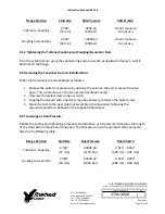
Flange Position
Stud Size
50% Pressure
50% Stretch
Turbine to Coupling
2.784"
[71 mm]
9000 psi
[620 bar]
Do not measure
Do not use
Coupling to Generator
2.283"
[58 mm]
10000 psi
[690 bar]
Do not measure
Do not use
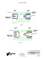
9.1.1 Tightening the Turbine/Coupling and Coupling/Generator Nuts
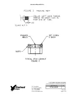
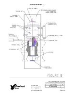
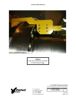
Turn the cylindrical nut using the spanner ring and pin wrench as depicted in Figure 5 until it
bottoms on the flange.
9.2 Removing the Tensioner from an Installed Stud
Puller tool removal is to accomplished as follows:
1.
Release the puller tool pressure by opening the valve on the pump. Leave the valve
open. This is automatic on the air‐operated hydraulic pump.
2.
Unscrew the puller screw using a wrench
3.
Tapping the wrench with a hammer may be necessary to loosen the puller screw.
4.
Move the tool to the next stud/nut assembly to be tensioned, following the
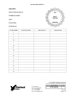
sequence/pattern as defined on the supplied data sheets.
9.3 Tensioning at Final Pressure
Repeat the pulling and tightening procedure stated above at full pressure. Measures the length
of the studs after all have been tensioned. The final pressure and required stretch values are
listed in the following table
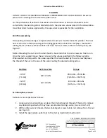
Flange Position
Stud Size
Final Pressure
Final Stretch
Turbine to Coupling
2.784"
[71 mm]
18000 psi
[1170 bar]
0.011" ‐ 0.014"
[0.28 mm ‐ 0.36 mm]
Coupling to Generator
2.283"
[58 mm]
20500 psi
[1240 bar]
0.019" ‐ 0.023"
[0.48 mm ‐ 0.58 mm]


