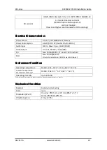
RC Series
RC3502SV-7311IR Installation Guide
04-2017-A
www.rivatech.de
10
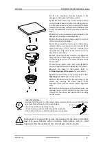
4.2. Adjusting angle of the camera
Adjust the angle of the camera by manually moving the corresponding parts following the directions
below.
Caution
!
The ambient light sensor shall be uncovered for its normal operation.
Caution
!
Tighten the tilt stopper after the tilt angle is confirmed.
Caution
!
Refrain from continuous rotation of the camera gimbal to a single direction as it
is linked with the IR-LED cable inside the dome.
DO
DI
1
1
C
C
+
DC12V
ETHERNET
RESET
MICRO
SD
DO
DI
1
1
C
C
+
DC12V
ETHERNET
RESET
MICRO
SD
ETHERNET
WIRE
DO
DI
1
1
C
C
+
DC12V
ETHERNET
RESET
MICRO
SD
DO
DI
1
1
C
C
+
DC12V
ETHERNET
RESET
MICRO
SD
ETHERNET
WIRE
DO
DI
1
1
C
C
+
DC12V
ETHERNET
RESET
MICRO
SD
DO
DI
1
1
C
C
+
DC12V
ETHERNET
RESET
MICRO
SD
ETHERNET
WIRE
1. Panning Adjustment
1. Perform the panning adjustment by turning the gimbal
bracket horizontally either clockwise or counter-
clockwise. If the panning angle is properly adjusted, fix
the gimbal bracket not to move when other parts are
adjusted.
2. Tilting Adjustment
Gimbal Bracket
2. Perform the tilting adjustment by moving the inner liner
vertically to upward or downward direction. Then,
tighten the screws on both sides of the gimbal bracket
to fix the tilt angle.
3. Horizontal rotation of lens
Camera Gimbal
Inner Liner
Gimbal Bracket
3. Rotate the inner liner clockwise or counter-clockwise for
the rotation of the lens.
*Please try not to leave fingerprints on the CDS light sensor.
Tilt Stopper


