RIB2312 Sapphire Gas Log Flame Fire
- 9 -
1/03/18 ©Rinnai
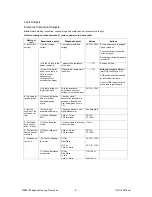
Fault Analysis
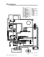
Electrical Component Analysis
Note:
Before starting inspection, check wiring and double check all connectors are tight
Before carrying out checks marked*, remove power cord from socket
Nature of
fault
Examination point
Diagnostic point
Values
Actions
A. Burner will
not light
(1) Is the voltage
correct
Check power point and
voltage
AC216 ~ 264V Ensure power cord is plugged
in and turned on
Check that power is supplied
to control panel
Ensure manual control panel is
turned ON
(2) Is the 3A fuse in the
power supply OK
* measure the resistance
of the fuse
<1
Replace if blown
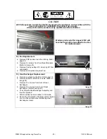
(3) Over Heat Switch
open circuit, faulty or
OHS connector
disconnected
(unit sparks for 2
seconds then stops)
*Measure the resistance of
the switch
<1
With power supply off
check
that OHS continuity is <1
OHS switch activation caused
by insufficient flue draw
Check if OHS lead is correctly
connected to Ignition pack
(4) Is there voltage to
the ignition pack
With the appliance
switched on check for
voltage at the ignition pack
AC216 ~ 264V
B. No spark at
Ignition probe
(5) Loose high tension
lead or cracked/
damaged ignition
probe
Check by visual
observation that spark is
between electrode and
Pilot head (gap 3.5mm ±
0.5)
C. Ignition
occurs but fire
pilot does not
light
(6) Check gas
pressure at test point
Check gas pressure with
digital manometer
See data plate
(7) Check Voltage at
POV
Yellow Yellow
POV terminals
DC12V
75 ~ 85
D. Pilot lights
but goes out
after 1 minute
(8) Check flame rod
current
Check on flame rod testing
connection plug
>15mA
E. Fire lights but
flame does not
modulate
(9) Check voltage to
POV
Yellow Yellow
POV terminals
DC12V
75 ~ 85
F. Fan does not
come on
(10) Check voltage at
fan motor
HI Fan
Blue-White
LO Fan
Yellow - White
AC110 ~ 130V
AC110 ~ 130V
(11) Check resistance
at fan motor
HI Fan
Blue-White
Lo fan
Yellow - White
170~190
240~260


