


– 47 –
⑩
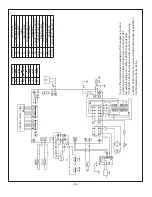
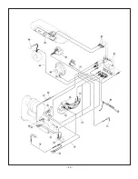
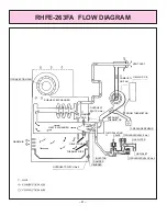
CONVECTION FAN
HEAT EXCHANGER
SUB HEAT EXCHANGER
THERMAL FUSE
⑧
BURNER
⑥
SOLENOID VALVE No.2
⑦
MODULATING
VALVE
③
COMBUSTI-
ON FAN
⑪
MAIN P.C.B
⑨
FLAME
ROD
⑤
SOLENOID VALVE No.1
GAS INLET
GAS FILTER
PRESSURE SENSOR
OVERHEAT
THERMISTOR
ROOM THERMISTOR
VENT ASS'Y
DAMPER
INJECTOR
OVERHEAT SWITCH No.2
OVERHEAT
SWITCH No.1
④
ELECTRODE
WARM AIR
RHFE-263FA FLOW DIAGRAM
Summary of Contents for RHFE-263FA 2
Page 14: ... 12 CUT AWAY DIAGRAM ...
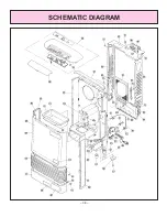
Page 40: ... 38 SCHEMATIC DIAGRAM ...
Page 41: ... 39 ...
Page 42: ... 40 ...
Page 43: ... 41 ...
Page 44: ... 42 ...
Page 55: ... 53 ...


