background image

 3

WARNING

IMPROPER INSTALLATION, ADJUSTMENT, ALTERATION, SERVICE OR
MAINTENANCE CAN CAUSE PROPERTY DAMAGE, PERSONAL INJURY OR
LOSS OF LIFE.

INSTALLATION AND SERVICE MUST BE PERFORMED BY A QUALIFIED
INSTALLER, SERVICE AGENCY OR THE GAS SUPPLIER.

Inbuilt Fire

Table of Contents

Limited warranty ............................................................................................................ 2
Contacts ........................................................................................................................ 3
Specifications ................................................................................................................ 4
Dimensions ................................................................................................................... 4
Important points / usage and installation musts ............................................................... 5
Technical specifications ................................................................................................. 7
For your safety read before operating heater .................................................................. 8
Operation....................................................................................................................... 9
Location......................................................................................................................... 10
Venting .......................................................................................................................... 12
Gas connection .............................................................................................................. 12
Electrical connection ...................................................................................................... 13
Log installation ............................................................................................................... 14
Testing and commissioning ............................................................................................ 15
Maintenance instructions ................................................................................................ 16
Wiring diagram .............................................................................................................. 18
Trouble shooting ............................................................................................................ 18
Exploded diagrams........................................................................................................ 19
Parts List ....................................................................................................................... 21
Installation notes ............................................................................................................ 22
Installation / commissioning checklist ............................................................................. 23
Installer details ............................................................................................................... 23

CONTACTS

zx

America Corporation

103 International Drive

Peachtree City

Georgia 30269

This manual applies to the following models only:

IB35RBN/US

IB35RBL/US

1-800-621-9419

www.rinnai.us

Summary of Contents for IB35RBL

Page 1: ...stallation and service must be performed by a qualified installer service agency or the gas supplier This heater has been designed to code ANSI Z 21 88a 2000 effective 7 1 2002 This appliance is only for use with the type of gas indicated on the rating plate This appliance is not convertible for use with other gases INSTALLER MUST LEAVE THIS MANUAL WITH THE UNITAFTER INSTALLATION OWNER RETAIN THIS...

Page 2: ... void the Warranty For the name of theAuthorized Distributor or Installer nearest you please contact your local HVAC dealer or gas service technician visit the Rinnai website www rinnai us callRinnaiat1 800 621 9419or writetoRinnai 103International Drive Peachtree City Georgia 30269 Proof of purchase is required You can show proof of purchase with a dated sales receipt or by completing and mailing...

Page 3: ...s 5 Technical specifications 7 For your safety read before operating heater 8 Operation 9 Location 10 Venting 12 Gas connection 12 Electrical connection 13 Log installation 14 Testing and commissioning 15 Maintenance instructions 16 Wiring diagram 18 Trouble shooting 18 Exploded diagrams 19 Parts List 21 Installation notes 22 Installation commissioning checklist 23 Installer details 23 CONTACTS zx...

Page 4: ... system Output 26 000 Btu hr Natural Gas 23 000 Btu hr Propane Gas Control Push button combination control valve Burners Ember bed flame and heat burner Warm Air Discharge Top front louvres Flue Natural draft Approved B vent system Ignition Electronic spark Power Supply 115v 60Hz Rating Plate Location Bottom right hand side door inside Weight 119 lb SPECIFICATIONS DIMENSIONS Gas inlet 3 8 MNPT ...

Page 5: ...n of the gas type if you are in doubt Included in the carton Customer operation information IMPORTANT Before using this product please read this manual carefully to make sure of proper use of the product 1 The installation must conform with local codes or in the absence of local codes the National Fuel Gas Code ANSI Z223 1 or the Canadian Installation Code CAN CGA B149 2 For information on gas typ...

Page 6: ...CSA C22 1 25 A gas appliance must not be connected to a chimney flue serving a solid fuel burning appliance 26 Do not restrict the war air discharge by placing articles in front of heater 27 This appliance must not be used for any purpose other than heating 28 Do not allow anyone to post articles through the louvres 29 Do not allow anyone to sit or lean against the appliance 30 DUE TO HIGH TEMPERA...

Page 7: ...E FRONT REMOVED CRACKED OR BROKEN REPLACEMENT OF THE GLASS SHOULD BE DONE BY A LICENSED OR QUALIFIED SERVICE PERSON Natural Gas Propane Gas Input Rate Btu hr Btu hr Pilot 200 200 13 000 11 000 High 34 000 31 000 WC WC Min 7 10 Max 10 5 13 Gas Connection Flue Termination Fan Combustion System Logs Ceramic Ignition System Operation Safety Devices Fan delay Bi metal strip Combustion Method Flue Type ...

Page 8: ... explosion D Do not use this appliance if any part has been under water Immediately call a qualified service technician to inspect the appliance and to replace any part ofthecontrolsystemandanygascontrol which has been under water OPERATING INSTRUCTIONS Visually check the pilot has lit and continue to hold the button for up to 15 seconds If the pilot does not remain alight push the button again an...

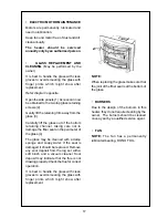
Page 9: ...heat TO DECREASE THE HEAT This is done by releasing the control buttons in order from left to right TO TURN THE UNIT OFF Press and release the buttons in order from left to right until all 3 buttons are in the OFF out position Ensure all burners are extinguished OPERATION FAN OPERATION On the LOW fire settings the fan can be operated on the LOW speed or OFF On the HIGH fire setting the fan runs au...

Page 10: ...east the width and depth of the heater 8 Installation location shall provide adequate combustion and ventilation air 9 A gas appliance must not be connected to a chimney flue serving a separate solid fuel burning appliance When positioning the heater the main points governing the location are 10 Before installing the heater inspect the chimney flue piping and or solid fuel burning fire place and r...

Page 11: ...ons a zero clearance kit must be used Combustible installation This may require a sheet of non combustible material to be laid under the heater or a layer of cement to be poured on the hearth The fireplace flue damper can be fully blocked open or removed for installation of the gas fireplace insert The fireplace and fireplace chimney must be clean and in good working order and constructed of non c...

Page 12: ... be installed vertically only If installation prevents this then there must be at least 4 feet of vertical flue before any bends The flue must not fall below horizontal at any stage There must not be more than 2 bends in any system Any horizontal section of flue must be less than 1 3 the length of vertical flue which follows it See diagram An approved B vent system must be attached by mechanical m...

Page 13: ... remove the cover A hole is provided on the right hand side of the junction box for a suitable electrical gland to be attached and the electrical supply to pass through 6 There are two wires one black one white that have been partially bared inside the box and a grounding earth pole with a green wire attached It is important that the power supply is connected to the correct wires and that the appl...

Page 14: ...rewdriver and remove excess material Note The ember bed material must be placed after the logs are fitted If the logs are to be removed for any reason the ember bed material must be removed first and replaced after the logs are refitted Any material that prevents the logs sitting flat on the burner top can upset the burning pattern and performance of the heater Replace glass and top glass retainer...

Page 15: ...rvice contact as listed on Page 3 It may take approximately 2 hours for the logs to achieve their full flame pattern and glow During the initial burning in period some smoke and smell may be experienced The heater should be run on the high position in a well ventilated room until these dissipate TESTINGAND COMMISSIONING It is the responsibility of the installer to check that under normal operating...

Page 16: ...l polishes to clean the casing while the fire is in operation Do not damage or distort any part of the heater Do not use wet cloth or spray cleaners on burners VENT MAINTENANCE The flue should be inspected annually for blockages and signs of damage VISUAL INSPECTION OF FLAME Check that the pilot and burner flames are operating normally Iftheflamesappeareitherveryshortorvery long and streaky or are...

Page 17: ...el taking care not to damage the fiber seal on the perimeter of the glass 4 The glass may be cleaned with a damp sponge and soapy water If the seal is damaged it should be replaced Remove any soot deposit from the log set with a soft brush and a vacuum cleaner Soot deposit may indicate that the flue is not drawing properly Check the flue for correct operation It is best to handle the glass with cl...

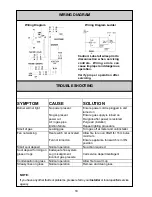
Page 18: ...low fire to run on HIGH for 15 minutes minimum Fan not turned on Ensure appliance fan switch is in ON position Small soot deposit Normal operation No action required Inadequate flue system Log misalignment Call service department agent Incorrect gas pressure Condensation on glass Normal operation Allow fire to warm up Streaky lines on glass Normal operation Remove and clean glass Soot deposit form...

Page 19: ...19 EXPLODED DIAGRAMS ...

Page 20: ...20 ...

Page 21: ...6mmx1 8 BSPT BFM690602 24 1 7904 PILOT BRACKET FRONT USA 25 1 7873 INJECTOR LPG 31 NG 1 7872 INJECTOR NG 51 LP 27 1 7937 GAS SUPPLY TUBE A IBMAN 28 1 7938 GAS SUPPLY TUBE B IBMAN 29 1 7948 PILOT TUBE IBMAN US 30 1 7955 INJECTOR BLOCK A B D 31 1 7952 INJECTOR BLOCK A B 32 1 7924 FRONT BURNER US ASSY PAINTED 33 1 4990 MAIN BURNER NG LPG USA FLAME 34 1 7044 CERAMIC LOG SET c w GRANULES 35 1 7258 AERA...

Page 22: ...ANEL IBR MK2 69 1 7857 FAN PARTITION PANL DGREASE USA 70 1 7221 FAN DISCHARGE GUIDE IBR 71 1 7222 FAN DISCHARGE GUIDE SHROUD IBR 72 1 7294 ANTI RATTLE BUTTON 73 1 7855 FLEXTUBE PANEL MOUNT ASSY USA 74 1 7984 PILOT ADAPTOR MAN USA 75 1 6635 FAN SWITCH R210 76 1 6643 MAIN GAS TUBE RETAINER 3 77 1 4995 GAS CONTROL ASSY FLAMEFIRES 78 1 6917 SPARKER UCH EC 79 1 7089 FAN SWITCH FLAME 3 POSITION 80 1 711...

Page 23: ...ation All burners light without delay 8 Is the end user fully aware of operating procedure NO YES Company name _______________________________________________________ Installers name ______________________________________________________ Address ______________________________________________________ ______________________________________________________ Phone __________________ Mobile ____________...

Page 24: ...zx Part Number 7918 ...

Reviews: