background image

 Installation & Servicing Instructions Rinnai E-Series 

39

6.6.9  Room Air System (indoor combustion air)

When using indoor air, Rinnai strongly recommends the use of an indoor air 

filter, P/N 808000025.
This boiler requires adequate combustion air for ventilation and dilution of flue 

gases. Failure to provide adequate combustion air can result in unit failure, fire, 

explosion, serious bodily injury or death. Use the following methods to ensure 

adequate combustion air is available for correct and safe operation of this boiler.

Important: Combustion air must be free of corrosive chemicals. Do not provide 

combustion air from corrosive environments. Appliance failure due to corrosive air is 

not covered by the limited warranty.

Combustion air must be free of acid forming chemicals such as sulfur, fluorine and 

chlorine. These chemicals have been found to cause rapid damage and decay and 

can become toxic when used as combustion air in gas appliances. Such chemicals 

can be found in, but not limited to bleach, ammonia, cat litter, aerosol sprays, cleaning 

solvents, varnish, paint and air fresheners. Do not store these products or similar 

products in the vicinity of this boiler.
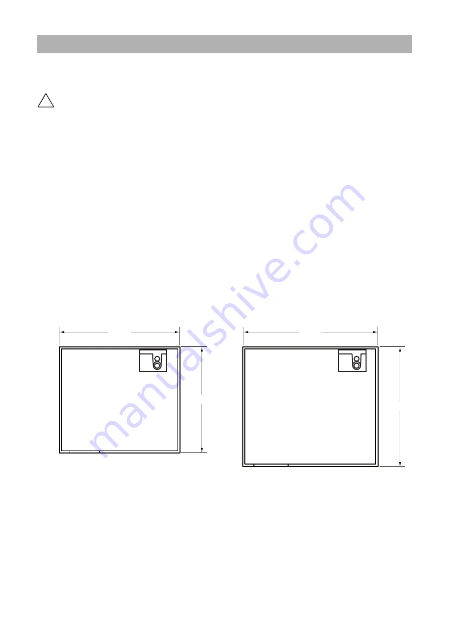
Unconfined Space:

An unconfined space is defined in NFPA #54 "as a space whose volume is not less 

than 50 cubic feet per 1000 Btu/hr (4.8 m3 per kW per hour) of the aggregate input 

rating of all appliances installed in that space. Rooms communicating directly with 

the space in which the appliances are installed, through openings not furnished with 

doors, are considered a part of the unconfined space." If the “unconfined space” 

containing the appliance(s) is in a building with tight construction, outside air may 

still be required for proper operation. Outside air openings should be sized the same 

as for a confined space.

Unconfined Space

91,300 BTU Boiler

Unconfined Space

200,000 BTU Boiler

25FT

NOTE: 8FT CEILING

25FT

36FT

NOTE: 8FT CEILING

36FT

Unconfined space                                                 


        figure 19

!

WARNING

Summary of Contents for E- Series

Page 1: ... manual provided with this boiler Installation and service must be performed by a licensed professional service agency or the gas supplier who must read and follow the supplied instructions before installing servicing or removing this boiler CAUTION The user manual is part of the documentation that is delivered to the installation s operator Go through the information in this manual with the owner...

Page 2: ...rking on heating and gas systems Subject to technical changes Changes may be made without notice to the illustrations process steps and technical data as a result of our policy of continuous improvement Updating of documentation Please contact us if you have any suggestions for improvements or corrections California Proposition 65 lists chemical substances known to the state to cause cancer birth ...

Page 3: ... Safety and general instructions 4 1 1 Designated use 4 1 2 Hazard definitions 4 1 3 Symbol definitions 4 1 4 The following instructions must be followed 5 1 5 Follow these instructions for the space heating water 6 1 6 Tools materials and additional equipment 6 1 7 Relevant Installation Service and User manuals 7 1 8 Disposal 7 2 Regulations and guidelines 7 3 Description of the boiler 8 4 Packag...

Page 4: ...jury death or substantial property damage WARNING Indicates the presence of hazards that can cause severe personal injury death or substantial property damage CAUTION Indicates presence of hazards that will or can cause minor personal injury or property damage CAUTION Risk of electric shock Indicates presence of hazards due to electric shock NOTICE Indicates special instructions on installation op...

Page 5: ...ing systems The boiler must be located in an area where leakage of the boiler or connections will not result in damage to the area adjacent to the boiler or to lower floors of the structure When such locations cannot be avoided it is recommended that a suitable drain pan be installed under the boiler The boiler must be installed in such way that the all components are protected from water dripping...

Page 6: ...L safe Sentinel X500 max concentration 50 Noble Noburst AL Fernox Alphi 11 Approved system cleaner Noble Noburst Hydronic System Cleaner Fernox F3 Cleaner Rhomar Hydro Solv 9100 Sentinel X400 The system cleaners from NoBurst Rhomar and Fernox are not to be used in the boiler The boiler must be closed off valved off from the rest of the system or not connected while the cleaners are in the system T...

Page 7: ...STALLATION This direct vent appliance must be installed by a licensed professional If you are not properly trained you must not install this unit IMPORTANT In the State of Massachusetts 248 CMR 4 00 5 00 For all side wall horizontally vented gas fueled equipment installed in every dwelling building or structure used in whole or in part for residential purposes including those owned or operated by ...

Page 8: ...the heat exchanger to the water in the central heating system By cooling down the exhaust gases condensate is formed This results in high efficiency The condensate which has no effect on the heat exchanger and the function of the boiler is drained through a condensate collector trap The boiler is provided with an intelligent control system CMS Control Management System The boiler anticipates the h...

Page 9: ...lug flue gas 1 1 1 Flue adapter Ø80 Ø3 pps UL appr 1 1 1 Air supply adapter Ø80 Ø3 pps UL appr 1 1 1 Lip ring flue pipe ø80 1 1 1 Wall mounting bracket HEX1 2S 1 1 1 Template 1 1 1 Installation Service Instructions 1 1 1 User information manual 1 1 1 Warranty document 1 1 1 ICSL book 1 1 1 User information manual 1 1 1 Warranty document 1 1 1 ICSL book 1 1 1 4 2 Transportation The boiler may be da...

Page 10: ...m the boiler and or around combustion air intake Spray cans containing chloro fluorcarbons Ammonium and or ammonium solutions Permanent wave solutions hair product Laundry equipment Chlorinated waxes and or cleaners Swimming pool chemicals based on chlorine Calcium chloride used for thawing Sodium chloride used for water softening Refrigerant leaks Paint or varnish removers Hydrochloric acid muria...

Page 11: ...r weight with its water content Take note of the necessary space around the boiler for installation of venting system pipework and servicing See drawing on pages 12 and 13 Drill the necessary holes using the template Install the mounting bracket to the wall The boiler must be installed using the included mounting hardware Lifting and carrying precautions To avoid personal injury please follow thes...

Page 12: ...G Left side gas pipe 9 8 250 g 3 4 M NPT H Left side supply pipe 5 9 150 f 0 59 x 1 M NPT 22mm J Left side return pipe 13 8 350 r 0 59 x 1 M NPT 22mm K Left side condensate pipe 15 9 405 c 0 87 22mm P Pipe length of g 1 26 Q Pipe length of c 1 6 40 R Pipe length of f and r 3 7 95 S Back Center of pipe c 1 25 T Back Center of pipe f g and r 1 9 49 V Pipe length concentric vent and air supply 7 177 ...

Page 13: ... 24 600 5 3 1 Clearances from boiler Minimum required clearances to combustibles Minimum required clearances to non combustibles Required service clearances All types All types All types inch mm inch mm inch mm Top of boiler 0 0 10 250 Back of boiler 0 0 0 Front of boiler 1 25 1 25 24 600 Left side of boiler 0 0 2 50 Right side of boiler 0 0 2 50 Floor Ground to bottom of boiler 0 0 10 250 30 762 ...

Page 14: ...9 0 AFUE efficiency rating 95 5 95 4 95 5 O2 at full load Electrical power consumption max W Electrical power consumption stand by W Current V Hz Fuse rating A Degree of protection acc EN 60529 Weight empty lbs kg 79 36 79 36 92 42 Water content CH gallon liter 0 9 3 3 0 9 3 2 1 3 4 8 After run time pump CH min PMS Water pressure min max PSI bar Supply temperature max F C Pump type UPER20 58 UPER2...

Page 15: ... air supply system It consists of a twin pipe connection that will accept 80mm flue and intake air or with the use of the included adapters 3 PVC CPVC flue and intake See further chapter 6 6 The pipes to be connected to the boiler must be cleaned before connecting in order to prevent dirt from entering and damaging the boiler NOTICE i Compression fittings Parts 1 Nut 2 Ferrule 3 Fitting Fitting in...

Page 16: ...lelwiththeboilerwithappropriate valves to prevent the chilled medium from entering the boiler The boiler piping system of a hot water boiler connected to heating coils located in air handling units where they may be exposed to refrigerated air circulation must be equipped with flow control valves or other automatic means to prevent gravity circulation of the boiler water during the cooling cycle S...

Page 17: ...and return connections on the plumbing kit V1 and V2 2 Open the bypass valve V4 3 Connect pump outlet hose H1 to the purge station BD1 and connect H2 to the inlet of the pump and place the other end in the pail 4 Connect drain hose H3 to the return side purge station BD2 5 Pour the system cleaner into a pail and follow the system cleaner instructions on circulation time and volume to be added to t...

Page 18: ...x are NOT to be used in the boiler The boiler must be closed off valved off from the rest of the system or not connected while the cleaners are in the system The system should then be drained and then thoroughly flushed with clean water to remove all the system cleaner Approved inhibitors Rhomar Pro tek 922 Sentinel X100 Noble Noburst AL inhibitor Connect the expansion tank to the system See chapt...

Page 19: ...sed loop If the boiler is to be installed in a system that utilizes zone pumps and not zone valves a low loss header plumbing kit should also be installed part number 804000061 If the pressure drop in the loop system is greater than the available head pressure from the boiler pump a low loss header plumbing kit should be used part number 804000061 NOTICE i NOTICE i pump index lines graph 1 0 2 4 6...

Page 20: ...cannot be used with an open type expansion tank 6 3 Underfloor heating system plastic pipes When using oxygen permeable tubing e g for underfloor heating systems the system must be separated using plate heat exchangers No recourse can be made to the terms of the limited warranty in the event of failure to observe the regulations pertaining to plastic underfloor heating pipes 6 4 Gas supply connect...

Page 21: ...ipped with external 3 4 M NPT thread Use appropriate sealing The connection to the boiler must include a suitable method of disconnection and a gas control valve must be installed adjacent to the boiler for isolation purposes The nominal inlet gas pressure measured at the boiler should be 7 W C 18 mbar for Natural gas Gas A Maximum pressure with no flow lockup or with the boiler running is 10 5 in...

Page 22: ...regulator is installed at least 6 to 10 feet upstream of the boiler Gas piping A sediment trap must be provided upstream of the gas shut off valve The boiler pipe is equipped with external 3 4 M NPT thread Use appropriate sealing The connection to the boiler must include a suitable method of disconnection A gas shut off valve must be installed adjacent to the boiler for isolation purposes The nomi...

Page 23: ...ndensate neutralizer designed to work with all boiler models The condensate neutralizer kit comes with all the necessary fittings and mounting material PVC pipe must be supplied by the installation contractor Rinnai part number 804000074 Do not drain the condensation water to the external rain gutter because of the danger of freezing and blockage of the drain Before putting the boiler into operati...

Page 24: ... 2 see table 9 The boiler is unsuitable to install on a common vent installation see also chapter 18 Do not connect the venting system with an existing vent or chimney Do not common vent with the vent pipe of any other boiler or appliance Vent connections must be firmly pressed together so that the gaskets form an air tight seal Refer to the instructions of the vent system manufacturer for compone...

Page 25: ...on pour les chaudières de catégories I II et IV doit présenter des tronçons horizontaux dont la pente montante est d au moins 1 4 par pied 21mm m entre la chaudière et le terminal de l évacuation pour les chaudières de catégories III la pente sera spécifi ée dans les instructions du fabricant de la chaudière pour les chaudières de catégories II et IV doit être installé de façon à empêcher l accumu...

Page 26: ...tric termination figure 12A Horizontal with parallel termination figure 12B Examples sealed combustions Vertical with parallel termination figure 12E Wall thickness for vent termination installation Minimum 100mm 4 Maximum 508mm 20 10 MINIMUM INSIDE EDGE T O INSIDE EDGE 12 OVER MAXIMUM SNOW LEVEL OR 24 WHICHEVER IS GREATER 6 6 2a Examples vent and air supply systems parallel ...

Page 27: ...of terminal and bends figure 13D Short termination with wall terminal figure 13A Termination with wall terminal on higher level figure 13B Examples roof terminals Examples wall terminals Wall thickness for vent termination installation Minimum 100mm 4 Maximum 508mm 20 6 6 2b Examples vent and air supply systems concentric ...

Page 28: ...amples vent and air supply systems PP Twin Pipe and Flex Vertical twin pipe termination figure 13F Horizontal twin pipe elbow termination figure 13G Horizontal twin pipe concentric termination figure 13H Horizontal twin pipe elbow termination below grade figure 13J ...

Page 29: ...Installation Servicing Instructions Rinnai E Series 29 Flex through chimney termination figure 13K Flex through B vent as a chase termination figure 13L ...

Page 30: ...ngers supports and restraints which are able to withstand all static and dynamic loading conditions which act upon the vent piping system and the associated Rinnai boiler Hangers supports and restraints shall be 100 corrosion proof UV resistant and impact resistant Exhaust vent pipe MUST be securely fastened to the structure to avoid movement The first hanger support MUST be located directly after...

Page 31: ...ially on the boilers The boiler connection diameter is concentric 80 125mm to which the concentric ventingandairsupplysystemcanbefitted withorwithoutelbowpieces Themaximum permissible pipe length is set out in table 9 chapter 6 6 6 Room Air System indoor combustion air The boiler can use room air for combustion If this option is selected the boiler must be provided with a parallel vent system A si...

Page 32: ...he boiler 5 Pull the rubber seal around the bottom of the exhaust connector 6 Push the exhaust connector in the boiler in the boiler exhaust pipe until CLICK 7 Push the rubber plug in open position in the O2 measuring opening and close the stop D Connect the parallel vent system 6 6 3 2 Installing air filter 1 Pull the 3 connections out of air intake of the boiler 2 Push the air filter into the ai...

Page 33: ...10 000 Btuh 3 kW 9 inches 30 cm for appliances 10 000 Btuh 3 kW and 50 000 Btuh 30 kW 12 inches 91 cm for appliances 50 000 Btuh 30 kW 4 feet 1 2 m below or to side of opening 1 foot 300 mm above opening C Clearance to permanently closed window D Vertical clearance to ventilated soffit located above the terminal within a horizontal distance of 2 feet 61 cm from the center line of the terminal E Cl...

Page 34: ...nditions must be considered and where necessary insulation of the inlet pipe may be required In cold and or humid weather water vapor may condense on leaving the vent terminal The effect of such water condensation must be considered The terminal must be located in a place not likely to cause a nuisance Cellular or Foam core PVC CPVC and Radel is not permitted for use with the boiler The applicatio...

Page 35: ...ir applications see sections 6 6 5 and 6 6 8 12 300 mm minimum 12 300 mm minimum 12 300 mm minimum INTAKE EXHAUST 12 300 mm minimum 12 300 mm minimum Terminal positions PVC figure 16 WARNING 15 386mm 6 148mm 11 268mm Closed door 1 25 4mm 10 254mm 1 25mm minimum clearance around vent pipes 2 50mm 2 50mm 1 25mm minimum clearance around hot water pipes 8 200mm 8 200mm Closet installation figure 17 10...

Page 36: ...jury death or substantial property damage Installation must comply with local requirements and with the National Fuel Gas Code ANSI Z223 1 For closet and alcove installation CPVC material instead of PVC must be used in a closet alcove structure Failure to follow this warning could result in fire personal injury or death All vent pipes must be connected and properly supported and the exhaust must b...

Page 37: ...t Total equivalent length Equivalent friction loss of PVC CPVC table 9 Fittings or Piping Equivalent PVC feet m 45 degree elbow 3 0 91 90 degree elbow 6 1 83 plastic pipe per foot 1 0 30 concentric vent kit 3 0 91 Centrotherm 3 PPs Equivalent lengths for piping fittings feet meters 45 degree elbow 6 1 83 87 degree long elbow 12 3 66 Termination Tee 12 3 66 Twin Pipe to Concentric Adapter 4 1 22 Lo...

Page 38: ...o warranty 3 Calculate the Compensation Factor Total CF T CF T CF V CF A The result is the setting for Parameter 73 Change parameter 73 according to this result See Chapter 10 1 how to change parameters Example of calculation E50C Eq lenth vent system taken from previous example 44 ft CF V 2 Altitude 7 200ft CF A 42 CF T 44 Parameter setting Par 73 44 Do not overcompensate the boiler by setting a ...

Page 39: ...and can become toxic when used as combustion air in gas appliances Such chemicals can be found in but not limited to bleach ammonia cat litter aerosol sprays cleaning solvents varnish paint and air fresheners Do not store these products or similar products in the vicinity of this boiler Unconfined Space An unconfined space is defined in NFPA 54 as a space whose volume is not less than 50 cubic fee...

Page 40: ... illustrated in figure 17 consideration must be taken for the design of the louvers or grills to maintain the required free area required for all gas utilizing equipment in the space If the free area of the louver or grill design is not available assume wood louvers will have 25 free area and metal louvers or grills will have 75 free area Under no circumstance should the louver grill or screen hav...

Page 41: ...n communicating directly with the outdoors through horizontal ducts each opening shall have a minimum free area of 1 in2 2000 Btu hr 1100 mm2 kW of total input rating of all appliances in the confined space Note If ducts are used the cross sectional area of the duct must be greater than or equal to the required free area of the openings to which they are connected When communicating indirectly wit...

Page 42: ... control 2 For E60SR E85SR and E110SR An external hot water tank connected on the secondary side of the optional plumbing kit seperately controlled by another device The capacity of the boiler must be defined by the installer The choice of the tank depends on the coil output The coil output of the tank must comply with the boiler output For additional information on piping and control of indirect ...

Page 43: ...ble to the cable harness terminal strip that connects to both the power switch on the front of the Control Tower and the terminal strip with positions 1 2 and 3 on the inside of the Control Tower The boiler must be electrically grounded in accordance with local codes or in absence of local codes with the National Electrical Code ANSI INFPA 70 RISK OF ELECTRIC SHOCK Once the main power supply is on...

Page 44: ...2 and 23 so that in the event the control is damaged the boiler will still fire based on outdoor reset A jumper should also be used when commissioning or trouble shooting the boiler Power stealing thermostats cannot be connected to terminals 22 and 23 NOTICE i NOTICE i Connection terminal E Series CAUTION 120 V 10 11 120 V 120 V 120 V Power supply Cylinder connection 8U 35 60 00 Outside sensor Bus...

Page 45: ... supply Cylinder connection 8U 35 60 00 Outside sensor Bus Controller 24 V 100 mA 1 2 3 4 5 6 7 8 9 12 13 14 15 16 17 18 19 20 21 22 23 24 25 26 27 N L N L N L N L CH DHW N A B DHW sensor three way valve Room therm On Off External safety contact Label all wires prior to diconnection when servicing or replacing controls Wiring errors can cause improper and dangerous operation CAUTION ...

Page 46: ...Installation Servicing Instructions Rinnai E Series 46 electrical ladder diagram figure 23a ...

Page 47: ...the system has been filled the automatic de aeration program starts when a program has been selected by pressing the button for Central Heating DHW or pump program of The program takes 17 minutes and stops automatically After this the unit will function normally See also Filling and de aerate the boiler and installation chapter 10 On a call for heating or hot water the control system will select t...

Page 48: ... kit is required to be installed 6 Mode button After briefly pressing a selection of the data chapters can be retrieved After pressing for 5 seconds it is possible to enter the code as described in chapter 12 3 7 Step button After briefly pressing the water pressure can be retrieved and pages per chapter can be retrieved After pressing for 5 seconds it switches from the Good state to technical rea...

Page 49: ...ents of the water system Before filling the heating system the complete system including all zones must be thoroughly cleaned and flushed to remove sediment Flush until clean water runs free of sediment Rinnai suggests using an approved system cleaner to flush the system but not the boiler Always use Rinnai approved antifreezes See the list at the end of this chapter Never use reverse osmosis deio...

Page 50: ...st AL Fernox Alphi 11 Approved system cleaner Noble Noburst Hydronic System Cleaner Fernox F3 Cleaner Rhomar Hydro Solv 9100 Sentinel X400 The system cleaners from NoBurst Rhomar and Fernox are not to be used in the boiler The boiler must be closed off valved off from the rest of the system or not connected while the cleaners are in the system The system should then be drained and then thoroughly ...

Page 51: ... Especially in the first week noises may be heard which indicate the presence of air The automatic air vent in the boiler will remove this air which means the water pressure can reduce during this period and therefore topping off with water will have to be done During normal use the following messages can occur with the necessary follow up NOTICE i Water pressure is too low 12 PSI flashing FILL wi...

Page 52: ...D Do not use this appliance if any parts have been under water Immediately call a licensed professional to inspect the appliance and to replace any part of the control system and any gas control which has been under water OPERATING INSTRUCTIONS 1 STOP Read the safety information above this label 2 Turn off al electrical power of the appliance 3 Set the thermostat or other operating control to the ...

Page 53: ...on until the code C123 is shown Press the STORE button to confirm the code code blinks1 x Now you have acces to the installer level There are 4 chapters Parameters Information chapter no adjustments possible Service chapter Error chapter no adjustments possible The content of the chapters is described on the following pages Press briefly the MODE button to select one of the 4 chapters i e PARA Pre...

Page 54: ...ting curve graph 1 1 1 4 7 14 F heating curve climate zone see also heating curve graph 4 32 F 10 0 F fine adjustment heating curve day temperature 8 to 10 F 11 0 F fine adjustment heating curve night temperature 8 to 10 F 14 10 F min gradient speed F min 0 28 F min 15 00 Booster after night decrease no 00 yes 01 23 4 F Frost Temperature 4 to 50 F 27 100 F Minimum T set CH 0 158 F 36 n a 43 max Ma...

Page 55: ... data in this table can be requested by the RS100 Most of the adjustments which are stated in this table are unnecessary when in combination with the Rinnai RS100 thermostat and will be taken care of by the RS100 itself and do not have to be adjusted For further information regarding to the RS100 thermostat refer to the Rinnai RS100 installation manual Parameter Info Service and Error chapters Tab...

Page 56: ...utton chapter PARA Press the STORE button The word Copy will appear and the factory settings are active again 12 Isolating the boiler Some situations require turning the entire boiler off By switching off the three buttons with the LED s for central heating hot water and pump program or the boiler is switched off Do not shut off the power of the boiler which means the circulation pump and the thre...

Page 57: ...boiler settings such as burner pressure and adjustment of the air quantity are unnecessary in most cases due to the fact that the boiler operates with a zero pressure control This means the correct gas quantity is controlled by the suction operation of the fan The fine adjustment of the zero pressure which is carried out at the factory is once only which means that adjusting of this value is unnec...

Page 58: ...owed on the input of the gas burner fitting is 14 inch W C 35mbar 13 2 Testing the Ignition Safety shut off device Switch off system using the Central Heating button and the DHW button Disconnect the plug and socket connection of the ionization cable Switch on the sytem using the Central Heating button and the DHW button Press the MODE button for 5 seconds The display will show COdE followed by an...

Page 59: ...e until 1 is shown alternately 1 and OFF will be shown Calibrate the O2 meter Place the probe of the O2 meter into the check point see fig 27 Press the button until the maximum value in kW is achieved The boiler will burn on full load value on display in kW value in BTU hr x3415 When adjusting from max to min load it is advisable to stop at medium load to allow the boiler to stabilize Adjusting qu...

Page 60: ...the code C123 Press the Store button to confirm the code code blinks 1 x Press the MODE button until SERV is shown Press the STEP button once until 1 is shown alternately 1 and OFF will be shown Press the button until the maximum value in kW is achieved The boiler will burn on full load value on display in kW value in BTU hr x3415 Measure the ionization When the boiler is in full load the ionizati...

Page 61: ...hours and full maintenance every 4 years or 8000 hours of operation whichever occurs first When doing this the circumstances of the boiler s location must be taken into account From this one can determine whether to deviate from this advice Please contact Rinnai for further guidance on the frequency and service requirements Contact details can be found on the back page of this manual 14 2 Inspecti...

Page 62: ...of the heating system See chapter 10 2 Filling the heating system 14 2 6 Checking venting systems Check the following points Is the prescribed combustion air flue system used Have the instructions for configuring the flue system as specified in the relevant Installation instruction for the flue gas system been observed Check air intake and or air filter and flue gas for obstruction pollution or da...

Page 63: ...ved from the hood and the venturi Clean the fan with a soft brush and a vacuum cleaner Replace the gasket and ensure that all gaskets of the fan parts are mounted correctly Heat exchanger every 4 year maintenance Check the heat exchanger for contamination Clean this if necessary with a soft brush and a vacuum cleaner Prevent debris from falling down into the heat exchanger Flushing the heat exchan...

Page 64: ...y downwards and remove it by pulling it forward Replace the gasket between condensate tray and heat exchanger with a new one Clean the condensate tray with water and a hard brush Check the condensate tray for leaks Step 3 Refitting is done in reverse order Note that all gaskets seals completely Make sure that during refitting the clamping rods they are put in the right position They should be turn...

Page 65: ...g combustion analyzer Verify proper operation after servicing Always reset the service interval counter after full maintenance interval every 4 years or 8000 hours of operation 14 3 1 Reset service interval counter At 8000 hours of use SERVICE will scroll across the display Good will display as well alternatively To reset the 8000 hour service notification Enter the 1st Tier Settings 123 Code Brie...

Page 66: ... 9 Control Tower CMS 10 water filter return CH 11 circulation pump 12 exhaust T1 supply sensor T2 return sensor Rinnai E60SR figure 41 13 combustion air supply 14 CSA Data Plate serial number 15 ASME NB CRN data plate P1 water pressure sensor 15 Parts of the boiler G gas pipe A supply central heating R return central heating C condensate pipe 4 2 1 3 13 5 12 6 C G T1 7 P1 R A 11 14 8 9 15 10 T2 ...

Page 67: ...lock 67 A T has been detected between flow and return sensor whereas the burner is not in operation After the T has disappeared the block will clear Block 85 The control has not detected a water flow The venting cycle is started If during this cycle water flow is detected the venting cycle is ended and the burner is released Error with a number in the last two positions Error 00 poor flame forming...

Page 68: ...r the average DT has disappeared the block will disappear Check the supply and return sensor for the resistance value and replace the defective sensor Check the installation for any external heat source and rectify this flue sensor temperature too high Check vent system flue sensor or thermostat contact open Call Rinnai flue sensor or thermostat contact closed Call Rinnai flue gas thermostat conta...

Page 69: ...pen there is power to the gas valve that the gas valve opens The minimum gas pre pressure during the start must be a minimum of 7 W C 17 mbar check the 24 Volts in the gas during ignition block s open position 2 There is a temperature difference between supply 3 and return 4 Boiler has gone out after ignition Due to insufficient ionization the burner has gone out after ignition Ionization flow ion...

Page 70: ...ow sensor failure controller failure Check the data in Error mode Boiler data during error 1 Error 14 2 Operational status 00 3 Flow temp 22 4 Return temp xx 5 kW burner 00 6 pomp xx variable values x3415 BTU hr A temperature of 36 is displayed at position 3 Check the wiring and or measure the resistance of the flow sensor The resistance should be approx 12 kOhm at 77 F See table in Appendix B If ...

Page 71: ...he sensor The wiring is OK but the error is repeated Remove the plug from the flow sensor as a result of which Error 36 occurs Replace the sensor Shut down of return sensor T2 Check the data in Error mode Boiler data during error 1 Error 32 2 Operational status 00 3 Flow temp xx 4 Return temp 230 5 kW burner 00 6 pomp xx variable values x3415 BTU hr Check the wiring check the wiring for the sensor...

Page 72: ...program into the new control unit Control unit error Software error control unit Replace the control unit Remove the E Prom from the defective control unit and place it onto the new control unit The controller will automatically load the program into the new control unit Electrical leakage to ground Moisture on controller PCB Check if there is water leaking on or in the boiler Stop water leak and ...

Page 73: ...epending upon the Eco temperature set 70 F is the default Check Info chapter Step 7 or temperature is higher than the Eco temperature set see RS100 installation instructions Check timer program and set room temperature 4 Three port valve is not circulating to central heating position Check wiring replace the three port valve motor Central heating installation gets hot without being requested 1 Key...

Page 74: ...Installation Servicing Instructions Rinnai E Series 74 ...

Page 75: ...e or explosion may result causing property damage personal injury or loss of life Do not store or use gasoline or other flammable vapors and liquids in the vicinity of this or any other appliance WHAT TO DO IF YOU SMELL GAS Do NOT try to light any appliance Do NOT touch any electrical switch Do NOT use any phone in your building Immediately call your gas supplier from a neighbor s phone Follow the ...

Page 76: ...NTRIC FLUE ADAPTOR 80 125 MM 808000023 X X X X X X 80 GASKET AIR INTAKE ø80 SHR 809000047 X X X X X X 81 FLUE GAS CONNECTOR 3 808000030 X X X X X X 82 AIR INTAKE CONNECTOR 3 808000031 X X X X X X 83 FLUE GAS PIPE OSS1 808000032 X X X X FLUE GAS PIPE OSS2 3 4 808000033 X X 84 PLUG MEASURING POINT PARALLEL FLUE PIPE 808000028 X X X X X X E85SRN E85SRP E110SRN E110SRP E60SRN E60SRP OSS1 OSS1 OSS2 84 ...

Page 77: ...Installation Servicing Instructions Rinnai E Series 77 Parts heat exchanger E Series 30 31 64 32 33 34 35 36 40 41 52 54 83 60 61 62 55 53 37 46 51 43 44 39 45 47 59 63 49 38 56 ...

Page 78: ...OSS1 ASME 807000019 X X X X HEAT EXCHANGER OSS2 ASME 807000020 X X BOILER TOOL KIT 809000024 X X X X X X 44 GASKET CONDENSATE TRAY OSS1 809000025 X X X X GASKET CONDENSATE TRAY OSS2 809000026 X X 45 CAP DE AERATOR SHR 3 PER PACKAGE 807000023 X X X X X X 46 DE AERATOR CHROME 807000024 X X X X X X 47 O RING ø13 94X2 62 DE AER 2 PER PACKAGE 809000028 X X X X X X 51 GASKET H E TOP PART OSS1 809000030 ...

Page 79: ...Installation Servicing Instructions Rinnai E Series 79 95 94 105 106 107 106a 109 111 121 138 93 92 122 104 103 91 308 304 112 113 94a Parts pipes E Series ...

Page 80: ...ILTER RETURN PIPE 807000029 X X X X X X 106 FILTER CAP 807000031 X X X X X X 106a O RING ø25 07 X 2 62 3WV 809000058 X X X X X X 107 NUT M35 ø30 809000059 X X X X X X 109 CONDENSATE COLLECTOR 809000081 X X X X X X 111 TRAP E SERIES 809000100 X X X X X X 112 O RING ø40X3 53 TRAP TRAY 809000084 X X X X X X 113 O RING 18 2X2 62 EPDM 3 PER PACKAGE 809000052 X X X X X X 113 O RING ø18 72X2 62 EPDM 3 PE...

Page 81: ...ing Instructions Rinnai E Series 81 Parts electrical components E Series 162 T1 supply sensor 160 T2 return sensor 166 T5 flue gas sensor 168 HLS high limit switch 161 P1 water pressure sensor 166 168 162 160 161 168 170 ...

Page 82: ...n Rinnai Part Number N P N P N P E85SRN E85SRP E110SRN E110SRP E60SRN E60SRP OSS1 OSS1 OSS2 140 HARNESS E 805000041 X X X X X X STICKER CONNECTION TERMINAL 805000046 X X X X X X CONNECTOR 2 POLE PURPLE 805000015 X X X X X X CONNECTOR 3 POLE GRAY 805000018 X X X X X X CONNECTOR 4 POLE BROWN 805000021 X X X X X X CONNECTOR 2 POLE BLACK 805000016 X X X X X X CONNECTOR 6 POLE BLUE 805000022 X X X X X ...

Page 83: ...stion 36 Vent Length SC 36 3 3x5 Sealed Combustion Adjustable Vent Length SC AVL3 3x5 Sealed Combustion 94 Elbow SC 94033 Wall Kit w Cap FSSCWMK35 Roof Kit w cap FSSCTRK35 Manufacturer Type Descriptions Parts DuraVent PolyPro 2 60 mm Twin Pipe Termination 2PPS HTP 3 80 mm Twin Pipe Termination 3PPS HTP 2 60 mm Single Pipe Term 2PPS HST 3 80 mm single Pipe Termination 3PPS HST 2 X4 60X100 mm Horizo...

Page 84: ...Plate White IAWP03W 3 Twin Pipe to 3 5 Concentric Adaptor ICTC0335 3 Base Support ISBS0387 3 Chimney Cover SS w PPs UV End Pipe ISCM03 3 Chimney Cover PPs UV Black ISCP03 3 Chimney Cover SS w SS End Pipe ISCS03 3 x 45 Elbow ISEL0345 3 x 87 Elbow ISEL0387 3 x 45 Elbow Long ISELL0345 3 x 45 Elbow Long PPs UV Black ISELL0345UV 3 x 87 Elbow Long ISELL0387 3 x 87 Elbow Long PPs UV Black ISELL0387UV 3 x...

Page 85: ...Telephone 800 463 9572 905 403 0264 Fax 905 403 9195 www ipexamerica com Simpson Dura Vent Telephone 518 463 7284 Fax 518 463 5271 sales duravent com www protechinfo com Rinnai Ubbink Telephone 800 621 9419 Fax 678 829 1666 www rinnai us York International Telephone 405 364 4040 877 874 7378 www york com products unitary CENTROTHERM Eco System Telephone 877 434 3432 Fax 518 618 3166 info centrothe...

Page 86: ...set Sensor Data and Resistance table NTC sensors Resistance table NTC Sensors Temp NTC 12K F 12k 77 F supply sensor T1 return sensor T2 DHW sensor T3 outside sensor T4 flue gas sensor T5 4 98 000 0 4 90 000 3 2 82 000 6 8 74 000 10 4 66 000 14 58 000 17 6 53 500 21 2 49 000 24 8 45 000 28 4 40 500 32 36 000 35 6 33 500 39 2 30 900 42 8 28 200 46 4 25 600 50 23 000 53 6 21 400 57 2 19 900 60 8 18 1...

Page 87: ... 804000061 Suitable for E60SRN E60SRP E85SRN E85SRP E110SRN E110SRP plumbing kit 1 figure 3 Appendix B Optional accessories Low Loss Header Clearances to combustible and non combustible is 0 inch for sides top front and floor ground The recommended service clearance to the bottom from the low loss header is 12 inches The plumbing kit is not intended to support the weight of the piping Appropriate ...

Page 88: ...g 1 Push the complete fitting over the pipe as far as possible Ferrule should be over the pipe completely 2 Turn the nut handtight clockwise 3 Use 2 wrenches one to hold the fitting on its place the other for tighten the nut clockwise in 3 4 turn 2 1 3 WARNING NOTICE i NOTICE i Do not overtighten these fittings when connecting flow and return pipe to the plumbing kit Max 150Nm 100 foot pounds ft l...

Page 89: ...w loss header from directly below the boiler to the left side of the boiler only The kit includes all the parts required to relocate the low loss header including all mounting brackets and material This kit provides an alternative to for installations with height limitations and allows for an alternative piping installation Kit 1 for boiler models E60SR E85SR and E110SR Rinnai part number 80400007...

Page 90: ...aner Rhomar Hydro Solv 9100 Sentinel X400 The system cleaners from NoBurst Rhomar and Fernox are NOT to be used in the boiler The boiler must be closed off valved off from the rest of the system or not connected while the cleaners are in the system The system should then be drained and then thoroughly flushed with clean water to remove all the system cleaner Approved inhibitors Rhomar Pro tek 922 ...

Page 91: ...Installation Servicing Instructions Rinnai E Series 91 ...

Page 92: ...the right to change the specifications and dimensions without prior notice Distributor for the USA R i n n a i A m e r i c a C o r p o r a t e 1 0 3 I n t e r n a t i o n a l D r i v e P e a c h t r e e C i t y G A 3 0 2 6 9 Toll Free 800 621 9419 Tel 678 829 1700 Fax 678 829 1666 E mail info rinnai us Internet www rinnai us E O E 800000055 03 2016 ...

Reviews: