


19
7 SERVICING
7.1 General
Once the appliance has been serviced, the benchmark Service Re-
cord must be completed. For UK only: It is important that the Bench-
mark Service Record is correctly completed and handed to the user.
Failure to install and commission the appliance to the manufacturers
instructions will invalidate the warranty. To ensure the continued safe
and efficient operation of the appliance, it is recommended that it is
checked and serviced at regular intervals. The frequency of servicing
will depend upon the particular installation conditions, but in general,
once per year should be adequate.
It is the law that any servicing work is carried out by competent person
such as a
Vokera
engineer, an approved service agent, British Gas, or
other Gas-Safe registered personnel.
The following instructions apply to the appliance, but it should be re-
membered that the domestic hot water system will also require atten-
tion from time to time.
7.2 Routine annual servicing
- Check the operation of the appliance and ensure it functions as de-
scribed in section 8 CHECKS, ADJUSTMENTS, AND FAULT FIND-
ING.
-
Compare the performance of the appliance with its design specifica
-
tion. The cause of any noticeable deterioration should be identified
and rectified without delay.
- Thoroughly inspect the appliance for signs of damage or deteriora-
tion especially the flue system and the electrical apparatus.
-
Check and adjust – if necessary – all burner pressure settings (see
8.3 CHECKING AND ADJUSTING BURNER PRESSURE).
-
Carry out an analysis of the flue gases (see 8.5 EXTERNAL FAULTS),
and visually check the condition of the entire flue assembly.
-
Compare the results with the appliance design specification. Any
deterioration in performance must be identified and rectified without
delay.
-
Ensure both flue venturis are clean and free from any debris or ob
-
struction.
- Ensure both the burner and heat exchanger are clean and free from
any debris or obstruction.
- Inspect all joints for signs of leakage and repair if necessary.
- Refer to the commissioning section and/or replacement of parts sec-
tion for detailed instruction if required.
7.3 Replacement of components
Although it is anticipated that this appliance will give years of reliable,
trouble free service, the life span of components will be determined by
factors such as operating conditions and usage. Should the appliance
develop a fault, the fault finding section will assist in determining which
component is malfunctioning.
7.4 Component removal procedure
To remove a component, access to the interior of the appliance is es-
sential. Isolate the appliance from the electrical supply and remove the
fuse. And when necessary, close all service valves on the appliance,
remove the appliance casing as described in section 4.8 CASING
REMOVAL. Drain the water content from the appliance via an outlet
or appropriate drain point. Ensure some water absorbent cloths are
available to catch any residual water that may drip from the appliance
or removed component.
Undertake a complete commissioning check as detailed in section 6
COMMISSIONING, after replacing any component.
b
Always test for gas soundness if any gas carrying components
have been removed or disturbed.
7.5 High limit thermostat
Carry out component removal procedure as described in 7.4 COMPO-
NENT REMOVAL PROCEDURE. Locate and remove the ten screws
that secure the air chamber cover.
Remove the air chamber cover.
Pull off electrical connections from the high limit thermostat, slacken
and remove retaining screws.
Replace in the reverse order.
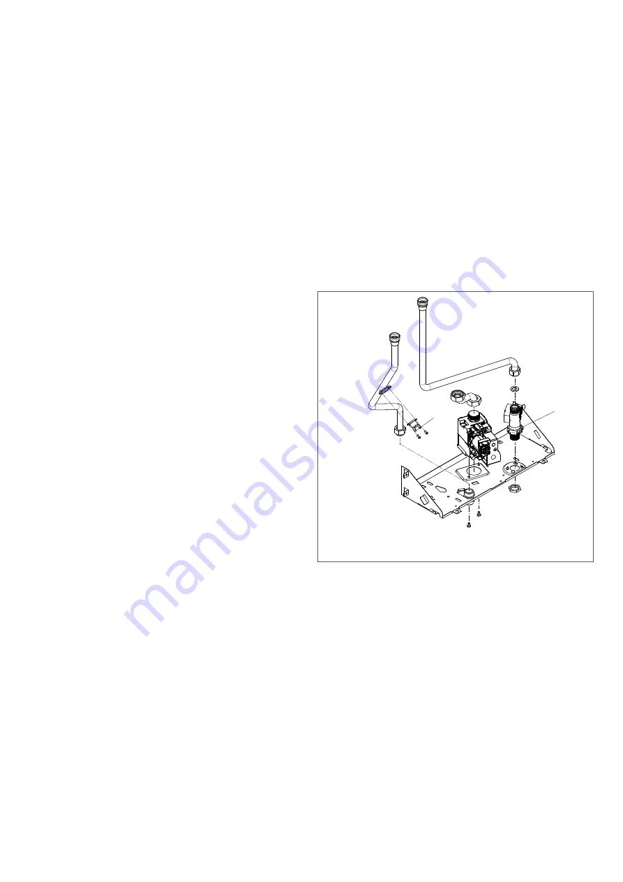
7.6 Flow switch
Carry out component removal procedure as described in 7.4 COMPO-
NENT REMOVAL PROCEDURE.
Remove the appliance casing as described in 4.8 CASING REMOVAL.
Disconnect the cold water inlet pipe from the bottom connection of the
flow switch.
Disconnect the outlet pipe from the top connection of the flow switch.
Detach the electrical plug/wires from the flow switch. Slacken and re
-
move the lock-nut that secures the flow switch to the lower frame. Re
-
place in the reverse order.
1
High limit thermostat
2
Flow switch
PRINTED CIRCUIT BOARD (PCB)
Carry out component removal procedure as described in 7.4 COMPO-
NENT REMOVAL PROCEDURE.
Remove the appliance casing as described in 4.8 CASING REMOVAL.
Carefully slide out the control panel until the lugs on the lower right and
left side of the panel are free from the slots on the appliance frame.
Remove the electrode lead from its clip on the PCB housing.
Locate and remove the two screws which secure the PCB cover & ter-
minal cover, then remove cover, after carefully taking note of all wiring
connections, disconnect all wiring from the PCB, locate and remove
the PCB securing screws, remove PCB.
Replace in the reverse order.
2
1
Summary of Contents for Vokera Easi-Flo LE
Page 27: ......


