


Maintenance
20008423
33
GB
6.1
Notes on safety for the maintenance
The periodic maintenance is essential for the good operation,
safety, yield and duration of the burner.
It allows you to reduce consumption and polluting emissions and
to keep the product in a reliable state over time.
The maintenance interventions and the calibration of
the burner must only be carried out by qualified, au-
thorised personnel, in accordance with the contents
of this manual and in compliance with the standards
and regulations of current laws.
Before carrying out any maintenance, cleaning or checking op-
erations:
disconnect the electricity supply from the burner by
means of the main switch of the system
close the fuel interception tap
6.2
Maintenance programme
6.2.1
Maintenance frequency
The gas combustion system should be checked
at least once a
year
by a representative of the manufacturer or another
specialised technician.
6.2.2
Checking and cleaning
Combustion
The optimum calibration of the burner requires an analysis of the
flue gases. Significant differences with respect to the previous
measurements indicate the points where more care should be
exercised during maintenance.
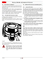
Combustion head
Open the burner and make sure that all the components of the
combustion head are:
– undamaged
– not deformed due to high temperature
– free of ambient dirt or dust
– free of rusted materials
– adequately positioned
Make sure that the gas outlet holes for the start-up, on the com-
bustion head distributor, are free of dirt or rust deposits.
In case of doubt, disassemble the elbow.
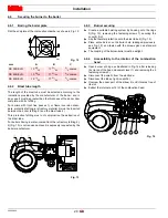
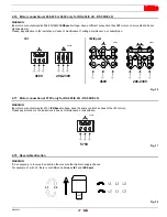
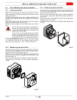
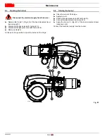
Measurement of detector current
Measurement of the detector’s signal (Fig. 41) with a Voltmeter is
not normally required since the flame signal’s intensity is shown on
the AZL...display and operating unit.
Min. value for a good work: 3.5 Vdc (AZL dosplay flame approx.
50%).
If the value is lower, it can depend on:
–
photocell positioned incorrectly;
–
low corrent (lower than 96V);
–
bad regulation of the burner.
To measure power, use a voltometer with a 10 Vdc scale, connect-
ed as illustrated in Fig. 41.
Gas leaks
Make sure there are no gas leaks on the conduit between the
gas meter and the burner.
Gas filter
Replace the gas filter when it is dirty.
Combustion
Adjust the burner if the combustion values found at the begin-
ning of the operation do not comply with the regulations in force
or, at any rate, do not produce good combustion.
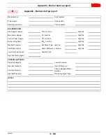
Use the appropriate card to record the new combustion values;
they will be useful for subsequent controls.
6
Maintenance
DANGER
DANGER
DANGER
Fig. 41
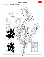
D3020


