


Technical description of the burner
20008423
9
GB
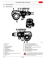
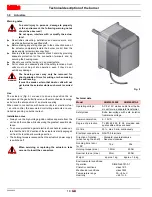
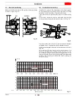
3.4
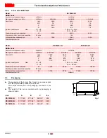
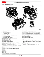
Overall dimensions
The maximum dimensions of the burner are given in Fig. 2.
Bear in mind that inspection of the combustion head requires the burner to be opened by rotating the rear part on the hinge.
The overall dimensions of the burner when open are indicated by L and R.
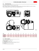
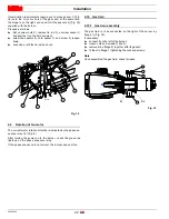
3.5
Burner equipment
The burner is supplied complete with:
Flange gasket
4 flange fixing screws M 16 x 50
4 screws to secure the burner flange to the boiler: M 18 x 70
2 spacers
Instruction manual and spare parts list
inch
A
B
C
D
E
F
G
H
I
L
R
S
RS 300/E LN
52 3/16“
20 1/2“
6 7/16“
12 5/16“ 23 5/32“
DN80
28 11/32“ 34 9/64“ 14 1/32“
46 1/4“ 41 17/32“ 12 19/32“
RS 400/E LN
52 3/16“
20 1/2“
6 7/16“
12 5/16“ 23 5/32“
DN80
30 1/2“
34 9/64“ 14 1/32“
46 1/4“ 41 17/32“ 12 19/32“
RS 500/E LN
52 3/16“
20 1/2“
6 7/16“ 14 17/32“ 23 5/32“
DN80
30 1/2“
34 9/64“
14
46 1/4“ 41 17/32“ 12 19/32“
A
B
C
F
E
D
I
G
H
R
L
R
S
S
Fig. 2
D3099


